
Testing method and system for long-distance multi-core cable

A multi-core cable and testing method technology, applied in the field of cable testing system, long-distance multi-core cable testing, and long-distance multi-core cable testing system, can solve the problem of consuming time and energy of staff, low work efficiency, and increasing the cost of testing equipment and other problems, to achieve the effect of simple test steps, easy operation, and improved work efficiency

Inactive Publication Date: 2014-03-26
BEIJING INST OF ELECTRONICS SYST ENG
View PDF9 Cites 16 Cited by
  • Summary
  • Abstract
  • Description
  • Claims
  • Application Information

AI Technical Summary

Problems solved by technology

The cable tester in the prior art is to manually test each core wire of the cable. With the increase of the number of cable core wires, it will consume a lot of time and energy of the staff, and the work efficiency is low.
Although there are some automatic test devices now, for the cables to be tested that have been fixed in the workplace, that is, when the process state cannot be changed and the two ends of the cables are far apart, such as pre-embedded cables, ship cables, and aircraft cables, it is necessary to pass The transfer cable connects the far end of the cable to be tested to the cable tester. With the different types and lengths of the cables to be tested, a large number of transfer cables are required, which greatly reduces the test efficiency and reliability and increases the testing equipment. cost

Method used


Image

  • Testing method and system for long-distance multi-core cable
  • Testing method and system for long-distance multi-core cable
  • Testing method and system for long-distance multi-core cable

Examples


Embodiment Construction

[0027] The present invention will be further described in detail below in conjunction with the accompanying drawings and specific embodiments.

[0028] Long-distance multi-core cable testing method of the present invention mainly comprises the following steps:

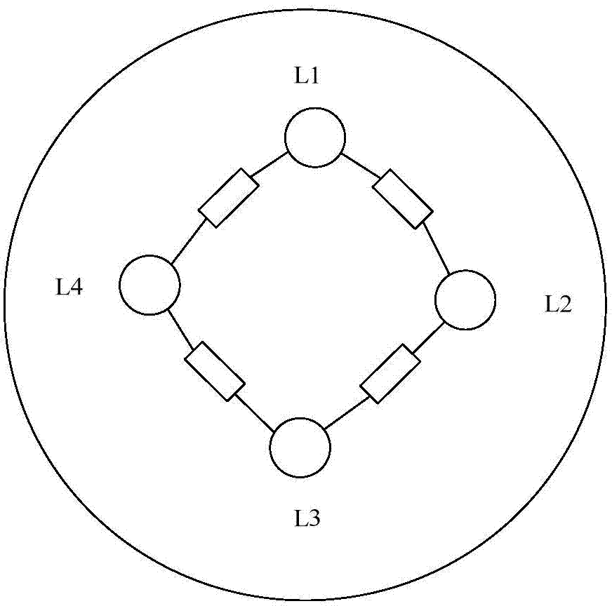
[0029] Between the core wires of the far-end connector plug of the multi-core cable, a resistor with fixed resistance is connected in series, and the near-end connector is connected to the cable tester;

[0030] On-resistance measurements on near-end cable testers for multi-core cables;

[0031] Remove the resistors between the core wires at the far end of the multi-core cable, and perform high-voltage insulation measurements at the near end of the multi-core cable.

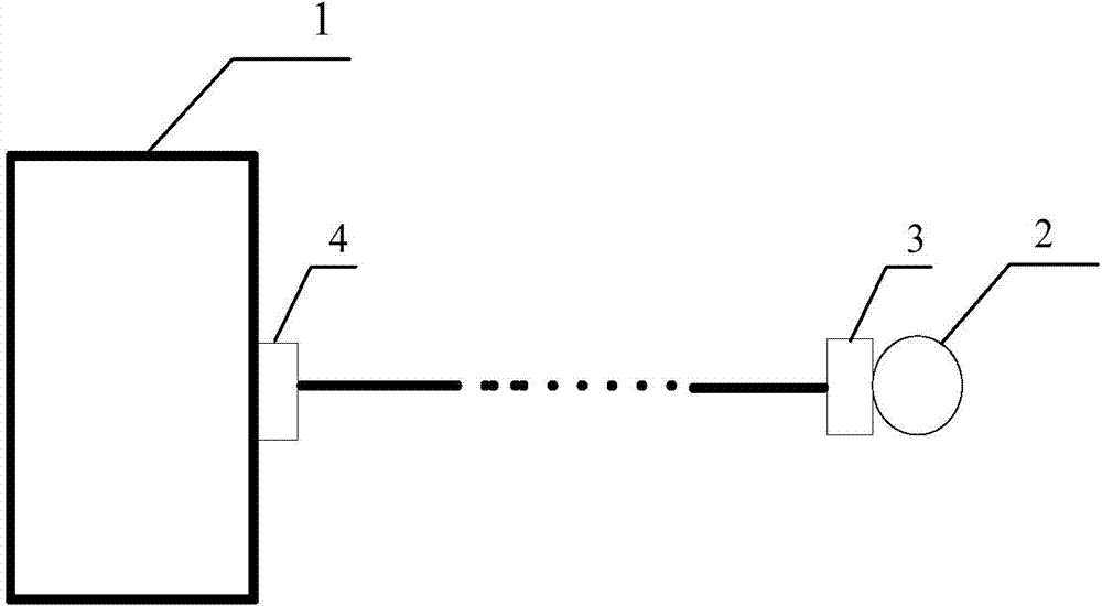
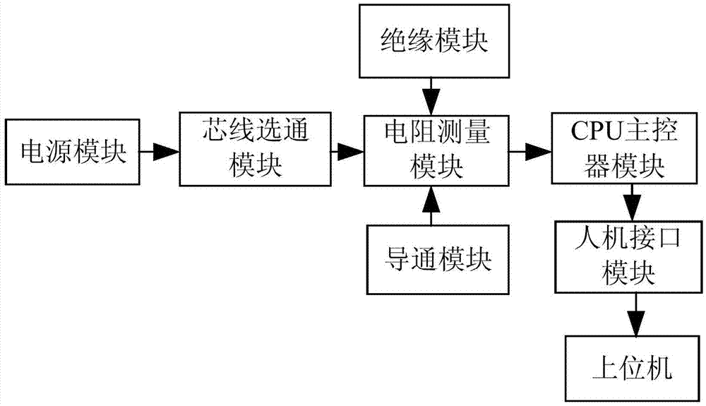
[0032] Such as figure 1 , 2 As shown, the test system for the long-distance multi-core cable test method includes a cable tester 1 and a termination device 2 . A near-end connector 4 is provided at the near end of the cable to be tested, and a far-end...


PUM


Abstract

The invention relates to a testing method and system for a long-distance multi-core cable. The testing method comprises the steps that resistors of known resistances are connected in series among core wires at the far end of the multi-core cable; on-resistances between the core wires are respectively measured at the near end of the multi-core cable; and the resistors of the known resistance at the far end of the multi-core cable are removed, and high-voltage insulating resistances between the core wires are respectively measured at the near end of the multi-core cable. The testing system comprises a cable tester and a terminating device. When the long-distance multi-core cable is tested via the method and system, the cable tester can test each core wire of the multi-core cable at the near end, and the terminating device is simple in structure in which only the resistors of the known resistances are connected in series among different jacks, so that a testing device is simple in operation and structure, and capable of testing the long-distance multi-core cable whose technical states cannot be changed.

Description

technical field [0001] The invention relates to a cable testing method, in particular to a long-distance multi-core cable testing method. [0002] The invention also relates to a cable testing system, in particular to a long-distance multi-core cable testing system. Background technique [0003] In order to ensure the reliability of the system, after the multi-core cable is welded, it is necessary to detect whether the cable cores are connected and insulated. The cable testers in the prior art all manually test each core wire of the cable. As the number of cable core wires increases, it will consume a lot of time and energy of the staff, and the work efficiency is low. Although there are some automatic test devices now, for the cables under test that have been fixed in the workplace, that is, when the process state cannot be changed and the two ends of the cables are far apart, such as pre-embedded cables, ship cables, and aircraft cables, it is necessary to pass The trans...

Claims


Application Information

Patent Timeline
Patent Type & Authority Applications(China)
IPC IPC(8): G01R31/02G01R27/14
Inventor 李景须陈会强许姣艾山
Owner BEIJING INST OF ELECTRONICS SYST ENG
Learn More