Pneumatic drying device of circulating fluidized bed

A circulating fluidized bed and airflow drying technology, which is applied in the direction of drying solid materials, lighting and heating equipment, heating to dry solid materials, etc., can solve problems such as poor circulation, slow moisture discharge speed, and difficulty in forming a fluidized state. , to achieve the effect of simple equipment structure, high drying efficiency and good fluidization state

Active Publication Date: 2014-03-26
云南彝医药开发有限公司
View PDF6 Cites 2 Cited by
  • Summary
  • Abstract
  • Description
  • Claims
  • Application Information

AI Technical Summary

Problems solved by technology

[0002] Invention patent ZL2010101628876 describes a drying equipment for powder materials. The drying equipment includes a fluidized bed main cavity for materials to form a fluidized state and dry them, and a sieve cage for separating materials from moisture. The circulatory system of the fluidized material circulation and the backflushing system used to remove the materials accumulated on the sieve screen to block the sieve screen have the following shortcomings: First, the air velocity in the main chamber of the fluidized bed is not high, and the water content It is difficult for materials with high rate and high viscosity to effectively form a fluidized state here; second, materials are easy to deposit at the dead corners of the sieve cage; slow gas discharge
The above deficiencies lead to poor fluidization state of materials, poor circulation, low output of drying equipment, and processing of materials with high water content and viscous materials is also very difficult

Method used


Image

  • Pneumatic drying device of circulating fluidized bed
  • Pneumatic drying device of circulating fluidized bed
  • Pneumatic drying device of circulating fluidized bed

Examples


no. 1 example

[0019] The first embodiment: a circulating fluidized bed airflow drying equipment.

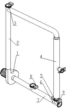
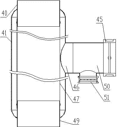
[0020] see figure 1 and figure 2 , the circulating fluidized bed airflow drying equipment includes fan 1, circulation pipeline I2, dust collector 4, regulating valve 5, inlet tee 6, circulation pipeline II7, the above components are blower 1 outlet, circulation pipeline I2, dust removal Air intake pipe 40 of device 4, ash discharge pipe 49 of dust collector 4, regulating valve 5, intake tee 6, circulation pipeline Ⅱ7, and fan 1 inlet are connected in sequence to form a circulation channel; A discharge valve 3 is installed on the feed port, a feed port is provided on the circulation pipeline II7, and a feed valve 8 is installed on the feed port, and another port of the air intake tee 6 is an air intake, and an air intake valve 9 is installed on the air intake.

[0021] The dust collector 4 of the circulating fluidized bed airflow drying equipment is a pulse bag dust collector. The pulse bag ...

no. 2 example

[0022] The second embodiment: a circulating fluidized bed airflow drying equipment.

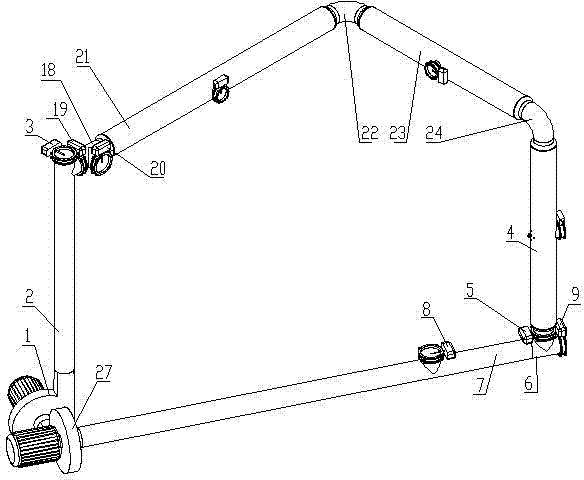
[0023] see image 3 and Figure 4 , the circulating fluidized bed air drying equipment includes fan 1, circulation pipeline I2, dust collector 4, regulating valve 5, inlet tee 6, circulation pipeline II7, dust collector 21, pipeline A22, dust collector 23, pipeline B24 , blower fan 27, the above-mentioned components are according to fan 1 outlet, circulation pipeline I2, dust collector 21 intake pipe 40, dust collector 21 ash discharge pipe 49, pipeline A22, dust collector 23 intake pipe 40, dust collector 23 ash discharge pipe 49, pipeline B24, dust collector 4 intake pipe 40, dust collector 4 ash discharge pipe 49, regulating valve 5, air intake tee 6, circulation pipeline II 7, fan 27 inlet, fan 27 outlet, and fan 1 inlet are sequentially connected to form a circulation channel; There is a discharge port on the circulation line Ⅰ2, and a discharge valve 3 is installed on the discharge po...


PUM


Abstract

The invention discloses a pneumatic drying device of a circulating fluidized bed. According to the pneumatic drying device, a draught fan (1), a circulation pipe I (2), a dust remover (4), a regulating valve (5), an air inlet tee joint (6) and a circulation pipe II (7) form a circulation passage. The draught fan (1) sucks airflow in through the air inlet tee joint (6). Under the action of the airflow, materials are in a fluidization state and flow in the circulation passage at a high speed, heat exchange and water exchange are rapidly carried out between the fluidized materials and the air, and then moisture is discharged out through an exhaust port of the dust remover (4). The process is carried out repeatedly until the moisture content of the materials meets the requirement.

Description

technical field [0001] The invention relates to an airflow drying equipment for granular materials and powder materials. Background technique [0002] Invention patent ZL2010101628876 describes a drying equipment for powder materials. The drying equipment includes a fluidized bed main cavity for materials to form a fluidized state and dry them, and a sieve cage for separating materials from moisture. The circulatory system of the fluidized material circulation and the backflushing system used to remove the materials accumulated on the sieve screen to block the sieve screen have the following shortcomings: First, the air velocity in the main chamber of the fluidized bed is not high, and the water content It is difficult for materials with high rate and high viscosity to effectively form a fluidized state here; second, materials are easy to deposit at the dead corners of the sieve cage; Gas discharge is slow. The above-mentioned shortcomings lead to poor fluidization state o...

Claims


Application Information

Patent Timeline
Patent Type & Authority Applications(China)
IPC IPC(8): F26B3/08
Inventor 贾平李冬梅
Owner 云南彝医药开发有限公司
Why Eureka
Try Eureka