
Steel support

A technology of steel frame and angle steel, which is applied in the field of metal profiles, can solve the problems of inconvenient transportation and difficult assembly of angle steel, and achieve the effects of convenient disassembly and transportation, simplified installation procedures, and strong practicability

Inactive Publication Date: 2014-03-26
昆山华英博五金建材有限公司
View PDF0 Cites 0 Cited by
  • Summary
  • Abstract
  • Description
  • Claims
  • Application Information

AI Technical Summary

Problems solved by technology

[0007] In order to solve the problem that the angle steel is not easy to assemble and transport, the object of the present invention is to provide a steel frame, which can be directly installed into a shelf of the desired shape, detachable, and can be combined arbitrarily

Method used

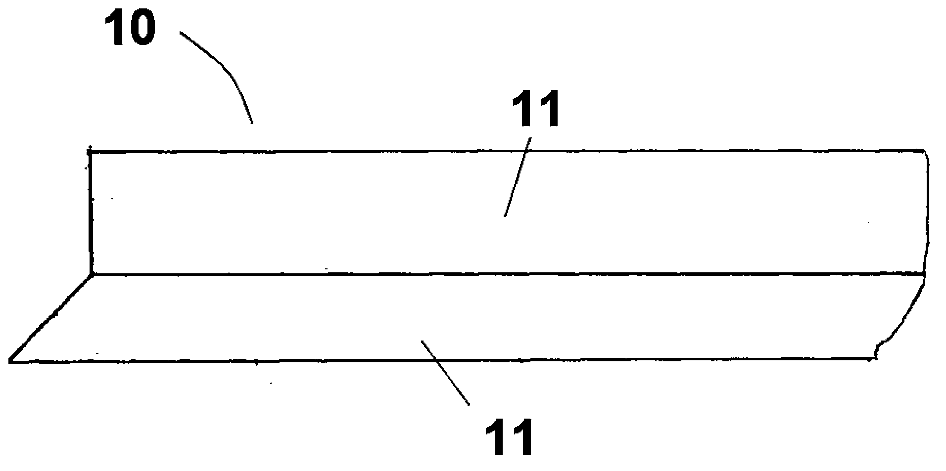

Image

  • Steel support
  • Steel support
  • Steel support

Examples


Embodiment Construction

[0020] The above-mentioned and other technical features and advantages of the present invention will be described in more detail through exemplary embodiments below in conjunction with the accompanying drawings.

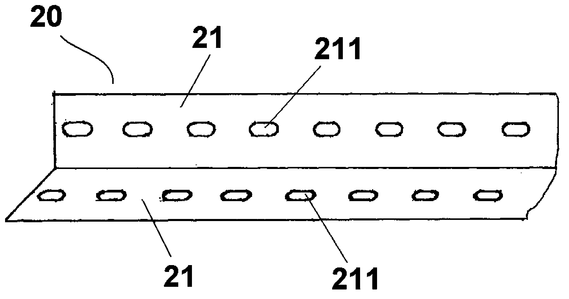
[0021] Such as figure 2 Shown is a schematic structural diagram of the first embodiment of the present invention. The steel frame 20 of the present invention includes two angle steel feet 21 perpendicular to each other, and several holes 211 are respectively arranged on each angle steel foot. The holes 211 can be connected with other steel frames through fixing parts, such as screws and nuts, so that they can be installed and combined at will according to user requirements. figure 2 The holes 211 shown in are arranged at equal intervals on the two angled steel feet 21.

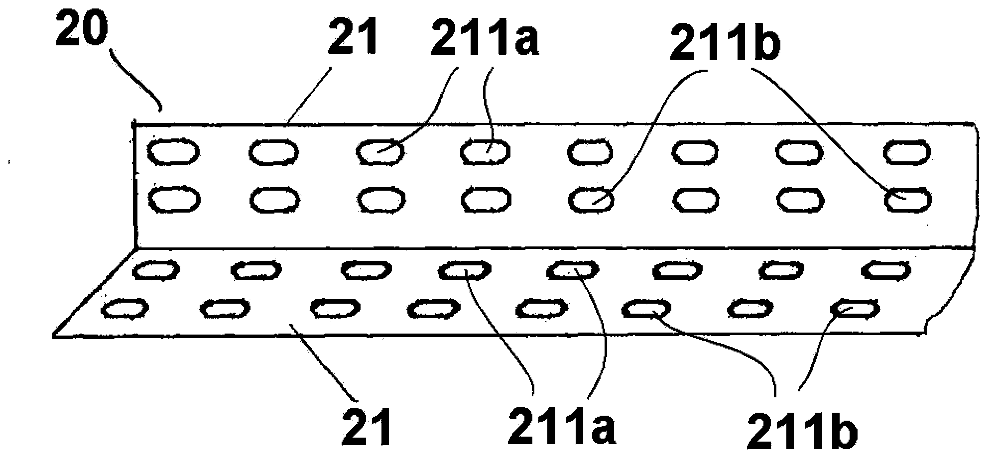
[0022] Such as image 3 Shown is a schematic structural diagram of the second embodiment of the present invention. Similar to the first embodiment, the steel frame 20 of the present invention i...


PUM


Abstract

The invention discloses a steel support which comprises two perpendicular angle steel feet, and a plurality of holes are formed in each angle steel feet at equal intervals. The steel support overcomes the defect that traditional angle steel needs to be welded again in assembly, and the steel support can be freely assembled and fixed according to needs, and is convenient to dismount and convey and high in practicability.

Description

technical field [0001] The invention relates to a metal profile, in particular to a steel frame. Background technique [0002] Angle steel, commonly known as angle iron, is a long strip of steel that is perpendicular to each other and forms an angle. Angle steel belongs to carbon structural steel for construction. It is a section steel with simple section. It is mainly used for metal components and frames of factory buildings. In use, it is required to have good weldability, plastic deformation performance and certain mechanical strength. The raw material billet for the production of angle steel is low-carbon square billet, and the finished angle steel is delivered in the state of hot rolling, normalizing or hot rolling. [0003] Angle steel can be composed of various stress components according to different needs of the structure, and can also be used as a connector between components. Widely used in various building structures and engineering structures, such as beams, ...

Claims


Application Information

Patent Timeline
Patent Type & Authority Applications(China)
IPC IPC(8): F16S3/00
Inventor 蔡浩
Owner 昆山华英博五金建材有限公司
Learn More