Buckle structure
A snap-on structure and sleeve technology, applied in the direction of connecting components, pins, mechanical equipment, etc., can solve problems such as danger, bolt slipping, rubber sleeve aging, etc.
- Summary
- Abstract
- Description
- Claims
- Application Information
AI Technical Summary
Problems solved by technology
Method used
Image
Examples
Embodiment Construction
[0020] In order to facilitate the understanding of the present invention, the present invention will be described more fully below with reference to the associated drawings. Preferred embodiments of the invention are shown in the accompanying drawings. However, the present invention can be embodied in many different forms and is not limited to the embodiments described herein. On the contrary, these embodiments are provided to make the understanding of the disclosure of the present invention more thorough and comprehensive.
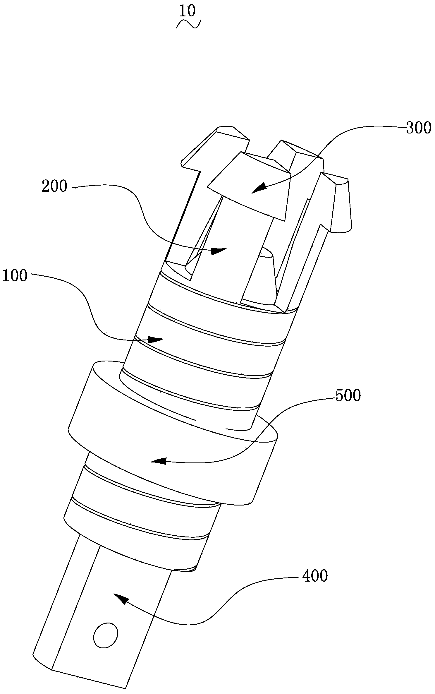
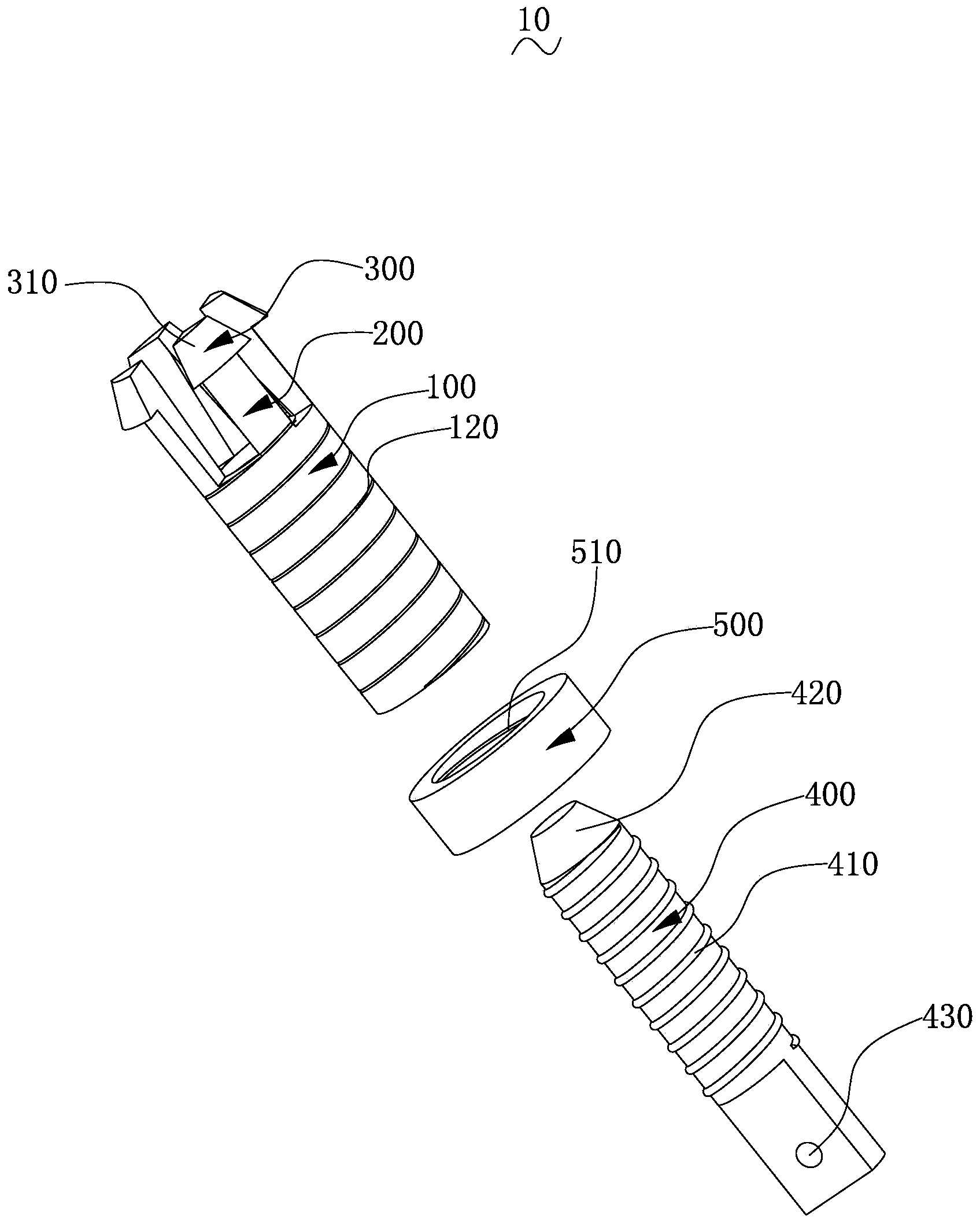
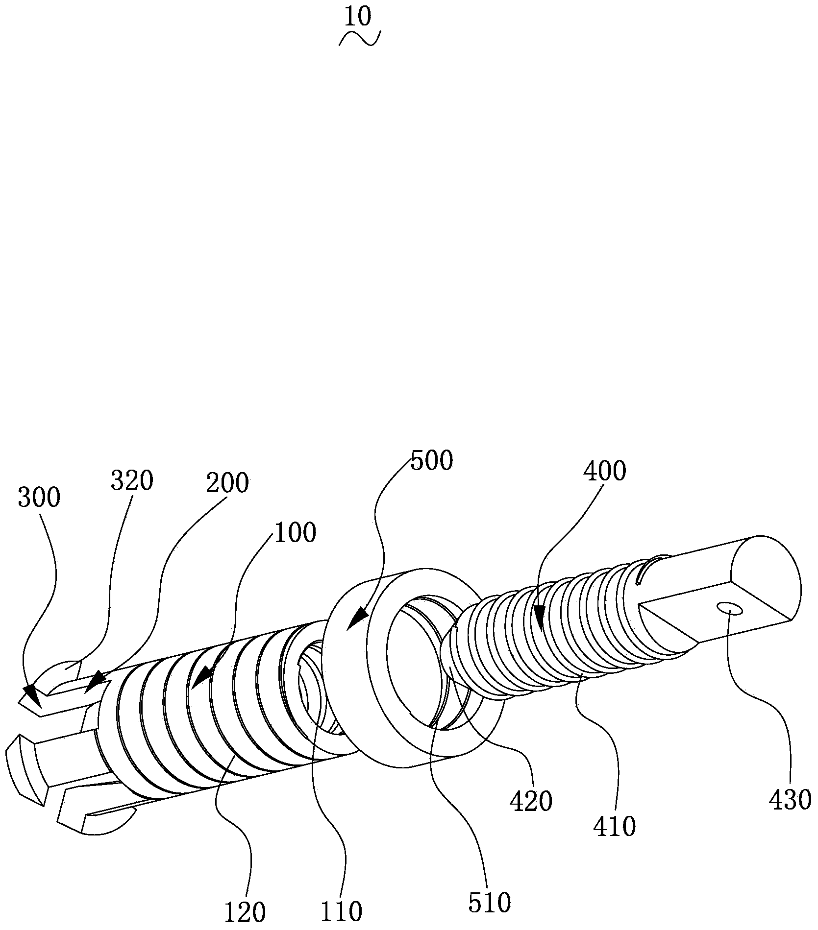
[0021] Such as figure 1 As shown, it is a schematic diagram of the buckle structure 10 of an embodiment. Please also refer to figure 2 and image 3 , which are respectively figure 1 The illustrated buckle structure 10 is an exploded view of two different viewing angles. The buckle structure 10 includes: a sleeve 100 , an elastic wall 200 , a protrusion 300 , a locking bolt 400 and a locking ring 500 .
[0022] The sleeve 100 is a cavity structure ...
PUM
 Abstract
Description
Claims
Application Information
 - Generate Ideas
- Intellectual Property
- Life Sciences
- Materials
- Tech Scout
- Unparalleled Data Quality
- Higher Quality Content
- 60% Fewer Hallucinations
Browse by: Latest US Patents, China's latest patents, Technical Efficacy Thesaurus, Application Domain, Technology Topic, Popular Technical Reports.
© 2025 PatSnap. All rights reserved.Legal|Privacy policy|Modern Slavery Act Transparency Statement|Sitemap|About US| Contact US: help@patsnap.com


