Capping head

A capping head and capping head technology, applied in the direction of flanged bottle caps, etc., can solve the problems of inconvenient operation, inability to adjust, and affect production efficiency, and achieve the effects of convenient operation, high production efficiency, and convenient adjustment

Active Publication Date: 2014-03-26
JIANGSU NEWAMSTAR PACKAGING MACHINERY
View PDF7 Cites 2 Cited by
  • Summary
  • Abstract
  • Description
  • Claims
  • Application Information

AI Technical Summary

Problems solved by technology

However, the pressure of this capping head is constant and cannot be adjusted. To change the pressure of the capping head, the capping head can only be disassembled to replace the inner spring 6, which is inconvenient to operate and affects production efficiency.

Method used


Image

  • Capping head
  • Capping head

Examples


Embodiment Construction

[0013] The capping head according to the present invention will be further described in detail below through specific embodiments.

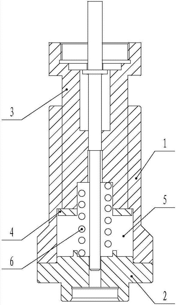
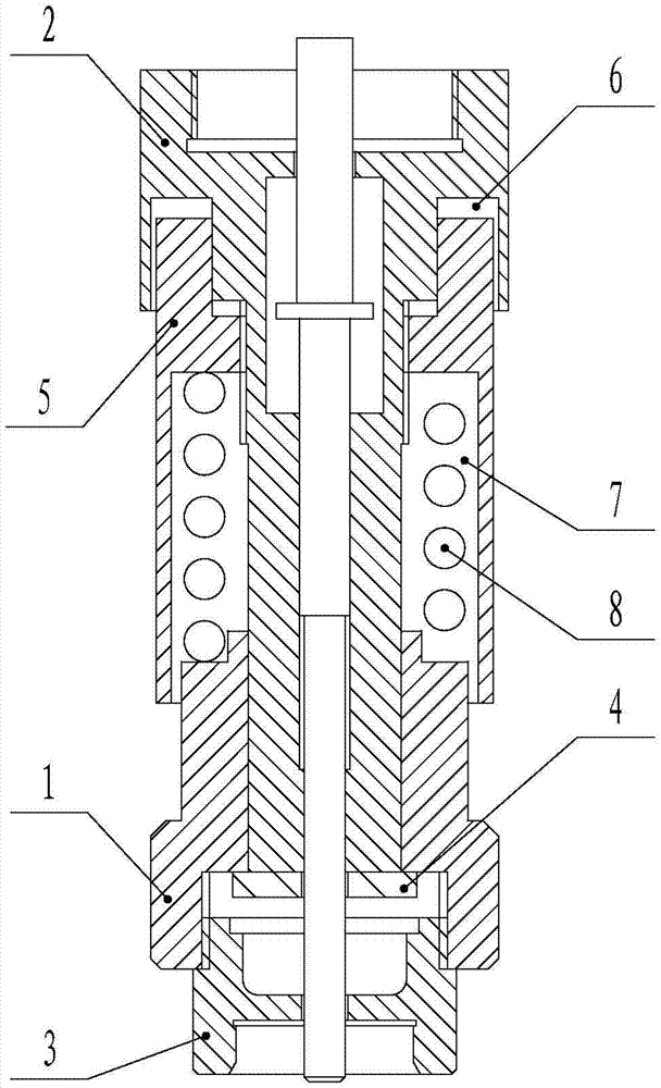
[0014] Such as figure 2 As shown, a capping head includes a mounting base 1 and a lifting block 2 matched with the mounting base 1. The lower half of the lifting block 2 is movably arranged in the mounting base 1, and the bottom of the mounting base 1 is provided with a cap removing head 3. The bottom of the lifting block 2 is provided with a positioning step 4 that is matched with the mounting seat 1, the upper half of the lifting block 2 is surrounded by an adjusting block 5, and the upper ends of the lifting block 2 and the adjusting block 5 are provided with mutually matched threads. The upper end is connected with the lifting block 2 through threads, and the position of the adjusting block 5 is adjusted in the vertical direction. The lifting block 2 is provided with a groove 6 at a position corresponding to the top of the adjusting block 5, an...


PUM


Abstract

The invention relates to a capping head. The capping head comprises an installation base and a lifting block which is matched with the installation base, the lower half portion of the lifting block is movably arranged in the installation base, a cap obtaining head is arranged on the bottom of the installation base, a positioning step which is matched with the installation base is arranged on the bottom of the lifting block, an adjusting block is arranged on the outer side of the upper half portion of the lifting block in a surrounding mode, the upper end of the adjusting block is connected with the lifting block, the vertical position of the adjusting block can be adjusted, a cavity is defined by the lifting block, the installation base and the adjusting block, a spring is arranged in the cavity, and the two ends of the spring abut against the adjusting block and the installation base respectively. The capping head is applicable to capping machines with pressure needing to be regulated.

Description

Technical field [0001] The invention relates to the technical field of capping machines, in particular to a capping head. Background technique [0002] At present, the capping head structure of the traditional capping machine is as follows figure 1 As shown, it includes a mounting base 1. The bottom of the mounting base 1 is connected with a cap removing head 2, a lifting block 3 is movably arranged in the mounting base 1, and the bottom of the lifting block 3 is provided with a step 4 matching the mounting base 1. The lifting block 3, installation A cavity 5 is formed between the seat 1 and the cap removing head 2, and a spring 6 is arranged in the cavity 5. [0003] When the cap removing head 2 obtains the bottle cap, the lifting block 3 moves downwards, compressing the spring 6. Under the action of the elastic force of the spring 6, the mounting seat 1 and the cap removing head 2 move down quickly to complete the capping, and the lifting block 3 moves upward to drive the install...

Claims


Application Information

Patent Timeline
Patent Type & Authority Applications(China)
IPC IPC(8): B67B3/10
Inventor 高擎宇沈军何德平
Owner JIANGSU NEWAMSTAR PACKAGING MACHINERY
Why Eureka
Try Eureka