
Electric heat therapy needle

A technology of electric heating and thermal components, applied in the field of therapeutic needles, can solve the problems of patient pain and high treatment costs, and achieve the effect of reducing pain

Inactive Publication Date: 2014-03-26
戴政祺 +1
View PDF5 Cites 4 Cited by
  • Summary
  • Abstract
  • Description
  • Claims
  • Application Information

AI Technical Summary

Problems solved by technology

However, the treatment costs of the above methods are quite high, and cause greater pain to the patient

Method used


Image

  • Electric heat therapy needle
  • Electric heat therapy needle
  • Electric heat therapy needle

Examples


Embodiment Construction

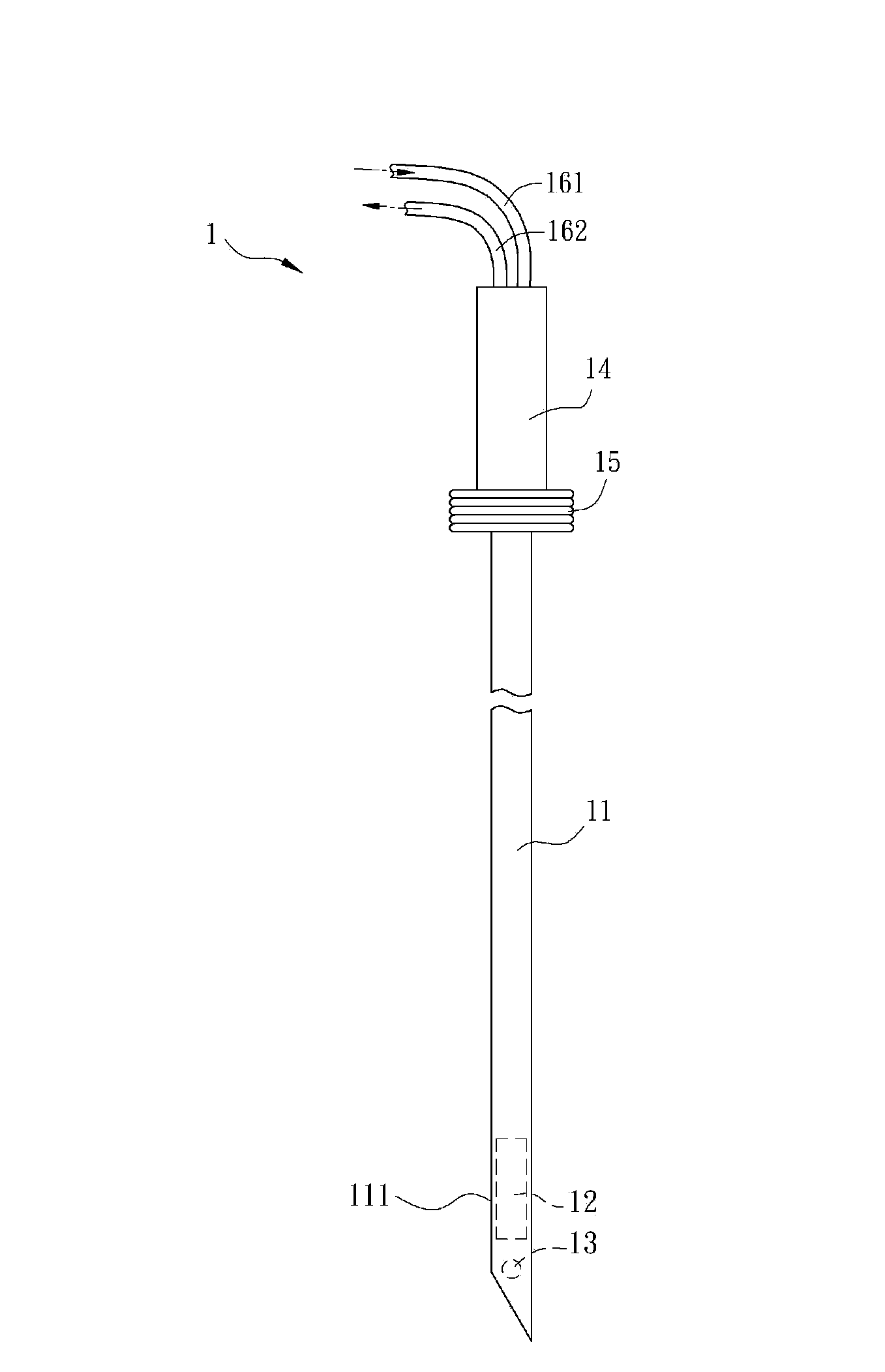
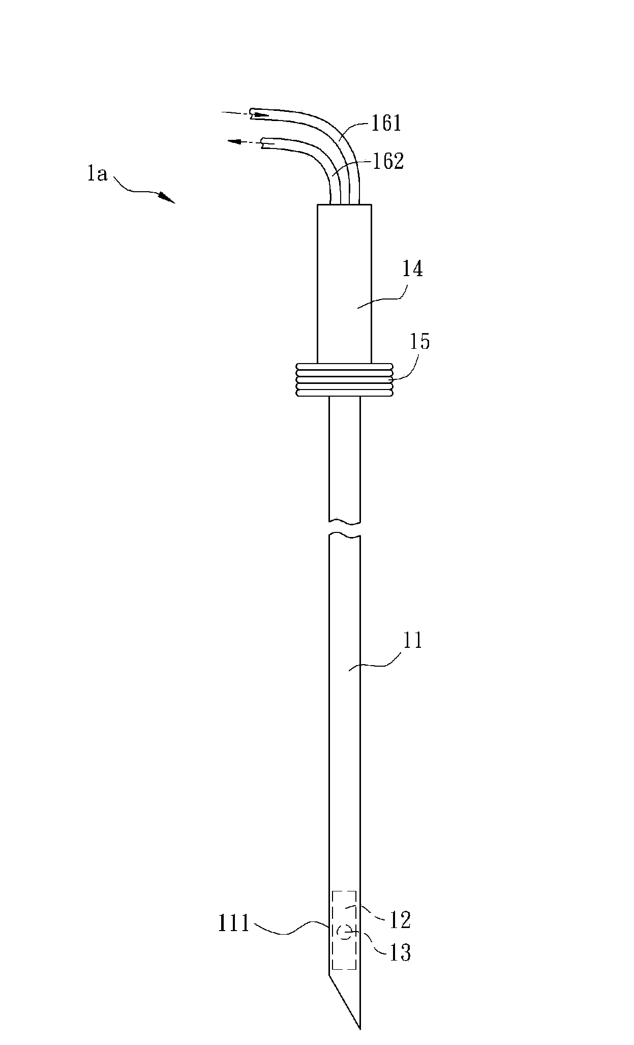
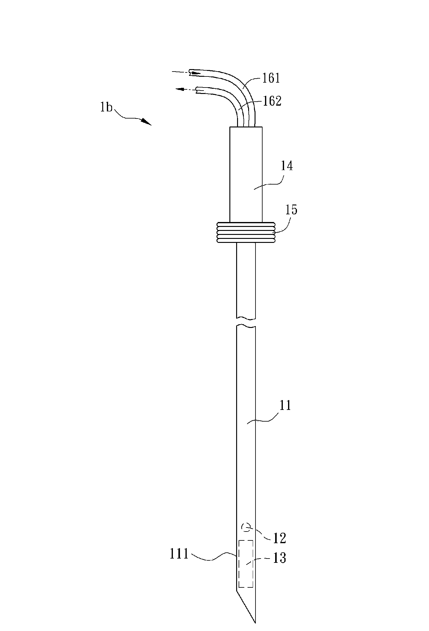
[0028] Hereinafter, an electrothermal therapy needle according to a preferred embodiment of the present invention will be described with reference to the relevant drawings, wherein the same components will be described with the same reference numerals.

[0029] figure 1 It is a schematic diagram of an electrothermal therapy needle 1 according to a preferred embodiment of the present invention. The electrothermal treatment needle 1 of the present invention can be used in conjunction with a power supply or a magnetic field generating device, through the power supplied by the power supply, such as direct current, alternating current, high frequency alternating current or pulse signal, or generated by the magnetic field generating device The alternating magnetic field can make the end of the electrothermal treatment needle 1 generate heat energy, thereby achieving the effect of cauterizing diseased tissues, such as enlarged spleens or tumors of animals or humans. Such as figure ...


PUM


Abstract

The invention relates to an electric heat therapy needle, comprising a body, a heat-generating assembly and a temperature sensing assembly. The body is provided with a metal tip part. The heat-generating assembly is disposed in the metal tip part. The temperature sensing assembly is disposed in the metal tip part. The electric heat therapy needle can burn tumor tissues and adjust temperature, can achieve high treatment efficacy at low cost, and can alleviate pains of a patient during a process of burning the tumor.

Description

technical field [0001] The present invention relates to a treatment needle, in particular to an electrothermal treatment needle. Background technique [0002] Existing thermotherapy methods for tumors include microwave hyperthermia, radiofrequency ablation hyperthermia, and ultrasonic focused hyperthermia. Among them, both microwave hyperthermia and radio frequency ablation hyperthermia are directly inserted into the tumor with needle-shaped electrodes; microwave hyperthermia uses the microwave radiator at the end of the microwave electrode to generate thermal effect, while radio frequency ablation hyperthermia uses the radio frequency current of the electrode needle , through ion excitation and conversion into heat energy, causing coagulation necrosis of local tumor tissue, so as to achieve the purpose of tumor treatment. However, the treatment costs of the above-mentioned methods are quite high and cause great pain to the patients. [0003] Therefore, how to provide a lo...

Claims


Application Information

Patent Timeline
Patent Type & Authority Applications(China)
IPC IPC(8): A61B18/12
Inventor 戴政祺黄世杰林锡璋陈永祥尤崇智
Owner 戴政祺
Learn More