Power converting device integrated with switch magnetic resistance motor driving and cell charging
A technology for power conversion devices and reluctance motors, which is applied to battery circuit devices, circuit devices, collectors, etc., and can solve problems such as high cost and complex structure
- Summary
- Abstract
- Description
- Claims
- Application Information
AI Technical Summary
Problems solved by technology
Method used
Image
Examples
Embodiment 1
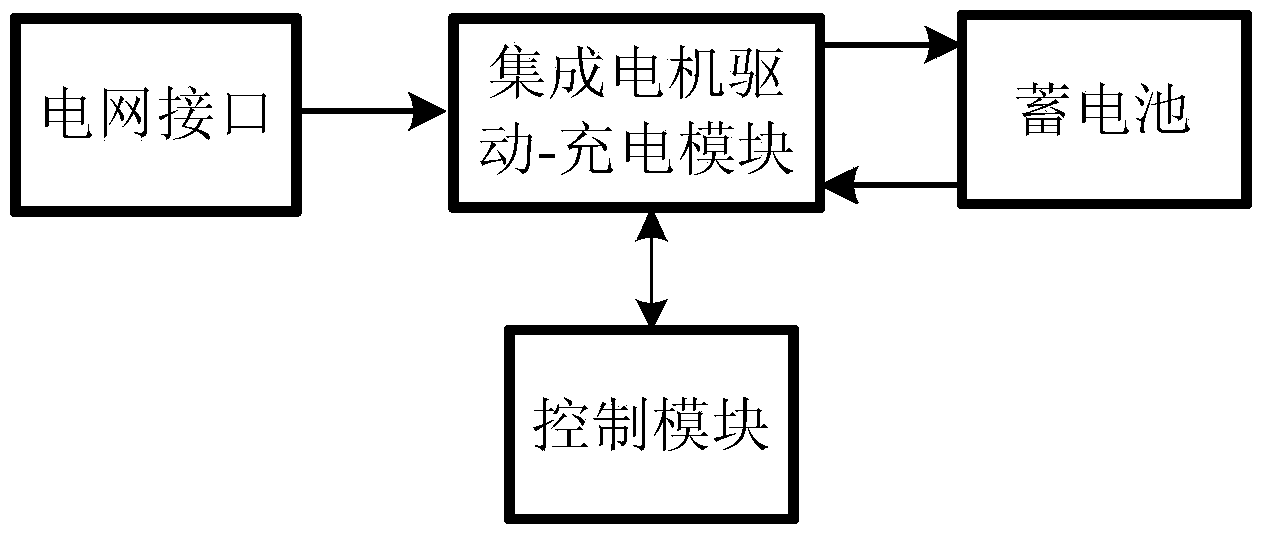
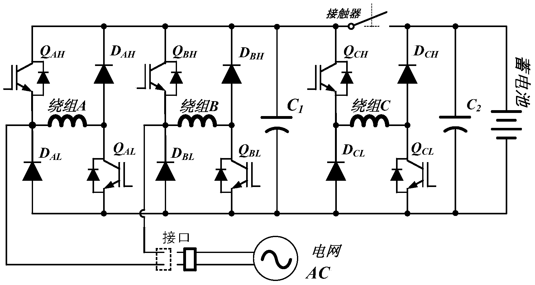
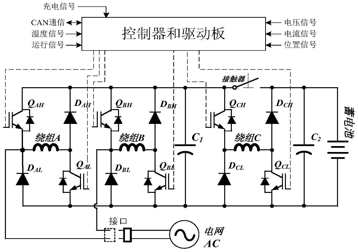
[0028] This embodiment provides a power conversion device integrating switched reluctance motor driving and battery charging, and its structural block diagram is as follows figure 1 As shown, it includes a control module and an integrated motor drive-charging module connected to the control module. The integrated electrode drive-charging module is connected to the grid interface and the battery respectively, and the charging and charging of the battery is realized through the integrated motor drive-charging module. The motor is driven by the battery. The power conversion device integrated with switched reluctance motor driving and battery charging described in this embodiment includes three-phase motor windings, which are winding A, winding B and winding C, respectively. An asymmetrical half-bridge circuit is formed at each phase motor winding, such as figure 2 As shown, the asymmetrical half-bridge circuit at winding A includes: motor winding A, one end of the motor winding...
Embodiment 2
[0039] As a further implementation, this embodiment provides a power conversion device that integrates switched reluctance motor drive and battery charging. On the basis of the above embodiments, the power conversion device in this embodiment also includes a locking structure. When charging The rotor is fixed by the locking structure. Since the phase inductance of a switched reluctance motor varies with the position of the rotor, fixing the position of the motor rotor helps to reduce the amount of variation in phase inductance with rotor position. Generally speaking, the rotor can be fixed in any position during charging. Through the analysis of the device, it is a better charging position to fix the rotor at the position where the stator pole centerline of the motor phase corresponding to the motor winding of the contactor switch and the rotor pole centerline coincide with each other when charging. The location is also suitable for charging at the same time. Since the charg...
Embodiment 3
[0048] The power conversion device integrated with switched reluctance motor drive and battery charging in this embodiment is set for a four-phase motor, so it includes a four-phase motor winding, see Figure 5 , including windings A, B, C, and D, forming four H-shaped asymmetrical half-bridges. Each half-bridge consists of semiconductor switching devices (Q AH and Q AL , Q BH and Q BL , Q CH and Q CL , Q DH and Q DL ), semiconductor diode (D AH and D AL 、D BH and D BL 、D CH and D CL 、D DH and D DL ), and one-phase winding (A-phase winding, B-phase winding, C-phase winding, D-phase winding) in the switched reluctance motor, in which the semiconductor switching device uses IGBT or MOSFET and other related switching devices, and the switching device has diodes in parallel. Also includes energy storage device (battery), capacitor C connected to the bus 1 and capacitance C 2 , There is also a contactor, the contactor disconnects both ends of the contactor through...
PUM
 Abstract
Description
Claims
Application Information
 - R&D
- Intellectual Property
- Life Sciences
- Materials
- Tech Scout
- Unparalleled Data Quality
- Higher Quality Content
- 60% Fewer Hallucinations
Browse by: Latest US Patents, China's latest patents, Technical Efficacy Thesaurus, Application Domain, Technology Topic, Popular Technical Reports.
© 2025 PatSnap. All rights reserved.Legal|Privacy policy|Modern Slavery Act Transparency Statement|Sitemap|About US| Contact US: help@patsnap.com


