
Rotatable Lighting System

A lighting system, a rotatable technology, applied in the field of lighting systems, can solve the problems of wire strands, poor wire contact, falling off and damage, etc.

Active Publication Date: 2016-03-23
吴江汾湖科技创业服务有限公司
View PDF3 Cites 0 Cited by
  • Summary
  • Abstract
  • Description
  • Claims
  • Application Information

AI Technical Summary

Problems solved by technology

However, in the known OLED lamps, the OLEDs and the power supply are connected by wires, which makes the general OLED lamps only rotate 180 degrees. It will cause the wires to be twisted, and then lead to poor contact or even fall off and damage. This problem has become an urgent problem to be solved at present.

Method used


Image

  • Rotatable Lighting System
  • Rotatable Lighting System
  • Rotatable Lighting System

Examples


Embodiment Construction

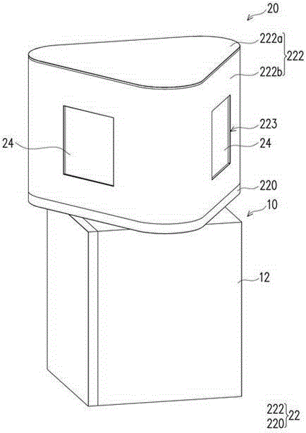
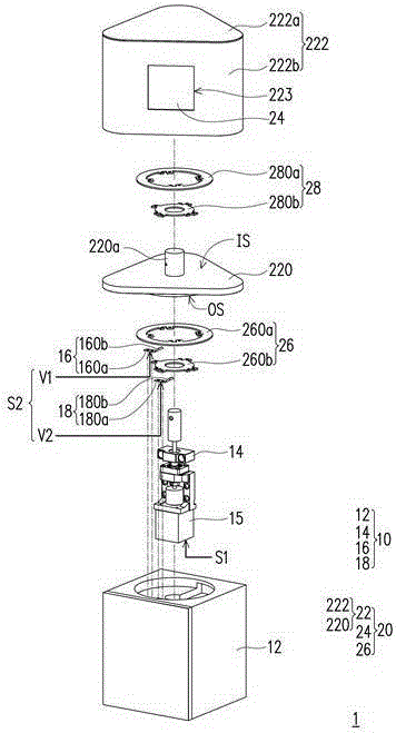
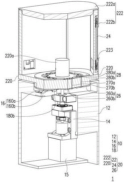
[0045] figure 1 It is a three-dimensional schematic diagram of a rotatable lighting system according to an embodiment of the present invention. figure 2 yes figure 1 An exploded schematic of the rotatable lighting system. image 3 yes figure 1 A cross-sectional schematic diagram of the rotatable lighting system. Figure 4 yes figure 1 A partial perspective view of the rotatable lighting system. Figure 5 yes figure 1 Another partial perspective view of the rotatable lighting system.

[0046] Please also refer to figure 1 , figure 2 ,and image 3 , the rotatable lighting system 1 includes a base 10 and a lighting device 20 . The lighting device 20 is disposed on one side of the base 10 . The base 10 includes a first housing 12 , a rotating shaft 14 , a first brush 16 and a second brush 18 . The lighting device 20 includes a second housing 22 , at least one light source 24 and a first electrode set 26 . Each component of the rotatable lighting system 1 will be des...


PUM


Abstract

A rotatable lighting system includes a base and a lighting device. The base includes a first shell, a rotating shaft, first and second brushes. The rotating shaft, the first and the second brushes are arranged on the first casing. The illuminating device includes a second shell, at least one light source and a first electrode group. The second casing includes a bottom fixed to the rotating shaft. The light source is arranged on the second casing. The first electrode group is disposed on the outer surface of the bottom and includes a first outer ring electrode and a first inner ring electrode electrically insulated from each other. The first brush is in electrical contact with the first outer ring electrode and the second brush is in electrical contact with the first inner ring electrode. The first outer ring electrode and the first inner ring electrode are respectively electrically connected to the light source.

Description

technical field [0001] The present invention relates to a lighting system, and in particular to a rotatable lighting system. Background technique [0002] Organic light-emitting diodes are semiconductor components that can convert electrical energy into light energy and have the advantages of high conversion efficiency, self-illumination, high brightness, high contrast, and wide viewing angles. Common uses are lighting, advertising lights, indicator lights, display Light-emitting components of panels or optical read-write heads, etc. [0003] Currently, organic light emitting diode lamps are usually designed to be rotatable in order to provide illumination or display in different directions and angles according to application requirements. However, in the known organic light emitting diode lamps, the organic light emitting diodes and the power supply are connected by wires, which makes the general organic light emitting diode lamps only rotate 180 degrees. It will cause th...

Claims


Application Information

Patent Timeline
Patent Type & Authority Patents(China)
IPC IPC(8): F21V21/30F21V23/06
CPCY02B20/30
Inventor 陈永坚江晋一
Owner 吴江汾湖科技创业服务有限公司
Learn More