Swinging supporting leg mounting structure, control device, system, control method and engineering machinery

A technology of construction machinery and installation structure, which is applied in the directions of transportation and packaging, vehicle maintenance, and lifting vehicle accessories, etc., can solve the problems that the outrigger cannot be fully deployed, easily overturned, and does not allow the outrigger to swing in a large range.

Active Publication Date: 2014-03-19
ZOOMLION HEAVY IND CO LTD
View PDF8 Cites 6 Cited by
  • Summary
  • Abstract
  • Description
  • Claims
  • Application Information

AI Technical Summary

Problems solved by technology

The defect of this swing-type outrigger control device is that in many occasions where the working space is narrow, the outriggers are not allowed to swing in a large range. At this time, the outriggers cannot be fully expanded. , prone to overturning

Method used


Image

  • Swinging supporting leg mounting structure, control device, system, control method and engineering machinery
  • Swinging supporting leg mounting structure, control device, system, control method and engineering machinery
  • Swinging supporting leg mounting structure, control device, system, control method and engineering machinery

Examples


Embodiment Construction

[0030] Specific embodiments of the present invention will be described in detail below in conjunction with the accompanying drawings. It should be understood that the specific embodiments described here are only used to illustrate and explain the present invention, and are not intended to limit the present invention.

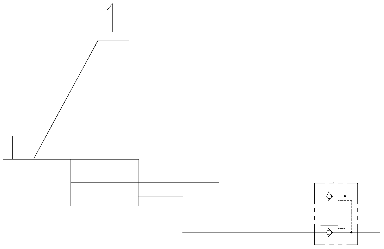
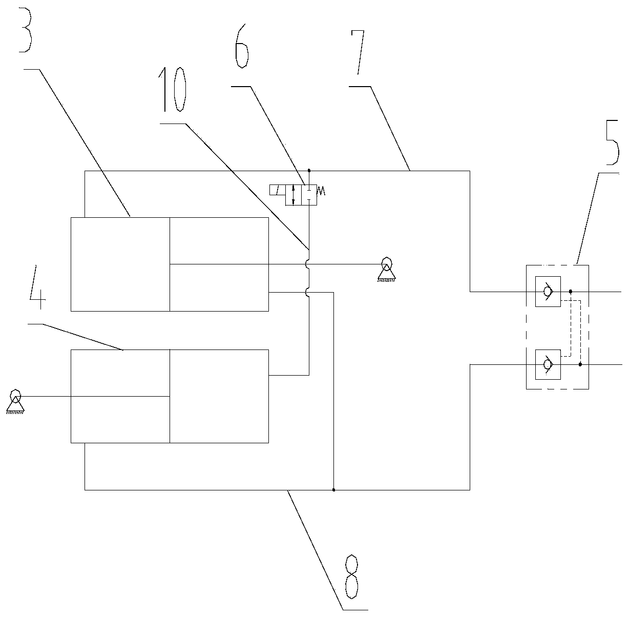
[0031] see figure 2 , according to a first aspect of the present invention, a swing leg installation structure is provided, the swing leg installation structure includes a swing leg, a body and a telescopic drive device, one end of the swing leg is hinged to the body, and the telescopic drive device is hinged to Between the swing outrigger and the body, the swing outrigger can be driven to move at least between the retracted position and the unfolded position. Specifically, the telescopic driving device includes a first driving cylinder 3 and a second driving cylinder 4 connected in series, preferably, the first driving cylinder 3 and the second driving cylind...


PUM


Abstract

The invention discloses a swinging supporting leg mounting structure which comprises a swinging supporting leg, a machine body and a telescopic driving device. One end of the swinging supporting leg is hinged to the machine body. The telescopic driving device is hinged to the swinging supporting leg and the machine body. The telescopic driving device comprises a first driving cylinder (3) and a second driving cylinder (4). One of the first driving cylinder (3) and the second driving cylinder (4) is hinged to the machine body, and the other one is hinged to the swinging supporting leg. When the first driving cylinder (3) and the second driving cylinder (4) are retracted completely, the swinging supporting leg is in a withdrawing position. When the first driving cylinder (3) and the second driving cylinder (4) extend out completely, the swinging supporting leg is in a stretching position. When one of the first driving cylinder (3) and the second driving cylinder (4) extends out completely and the other one is in a complete-retracted state, the swinging supporting leg is in a machine-body-rotating-preset-angle position. In addition, the invention discloses matching control method of a hydraulic control device, a control system, engineering machinery and the swinging supporting leg.

Description

technical field [0001] The invention relates to an installation structure of a swing outrigger. In addition, the invention also relates to a hydraulic control device, a control system, an engineering machine and a method for cooperating with the swing outrigger. Background technique [0002] Construction machinery such as concrete pump trucks usually need to use support devices to realize the support during work, so as to enhance the stability during work and avoid overturning caused by excessive work load. The supporting device generally includes two pairs of outriggers at the front and back, and each outrigger has two positions of retracting and supporting. When moving, the outriggers need to be retracted; during construction, the outriggers need to be unfolded to achieve support. [0003] In the prior art, outrigger-type construction machinery is divided into two categories according to the position when it is stowed: one is a swing-type outrigger, and the stowed positio...

Claims


Application Information

Patent Timeline
Patent Type & Authority Applications(China)
IPC IPC(8): B60S9/10
Inventor 王巧云
Owner ZOOMLION HEAVY IND CO LTD
Why Eureka
Try Eureka