a paper reel
A technology of filter paper and body, which is applied in the field of filter element production, and can solve the problem that both hands cannot complete the work of rewinding filter paper
- Summary
- Abstract
- Description
- Claims
- Application Information
AI Technical Summary
Problems solved by technology
Method used
Image
Examples
Embodiment 1
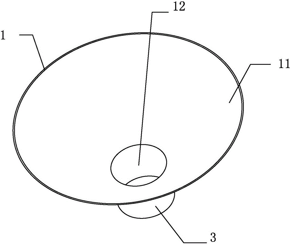
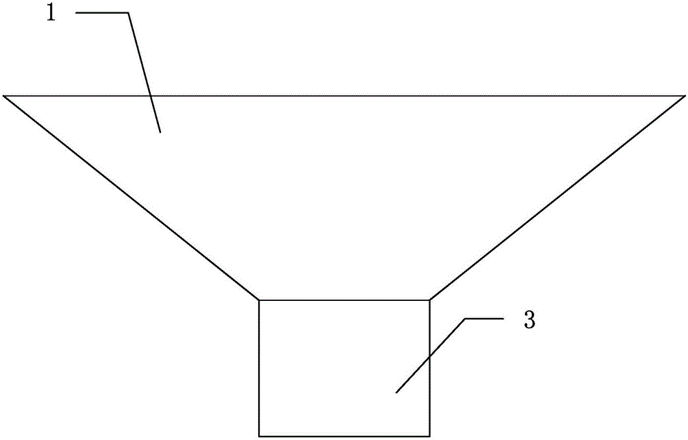
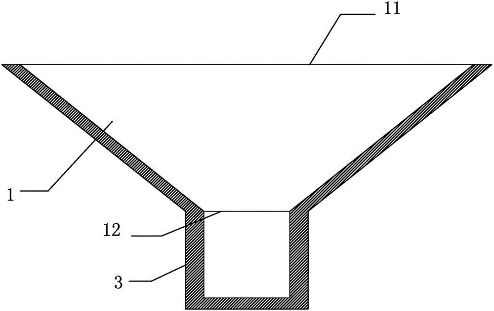
[0020] Such as Figures 1 to 4 As shown, a paper reel is used for rewinding filter paper, including a hollow body 1 with upper and lower ends open, the lower end opening of the body 1 is a round mouth, and the distance from the inner wall of the body to the central axis of the body is from It gradually decreases from top to bottom. The lower end of the body 1 is provided with a cylinder 3 with an inner cavity in the shape of a cylinder. The top of the cylinder 3 is open and communicates with the lower opening 12. The inner diameter is consistent and the diameter of the lower end opening 12 is the same. The bottom end of the cylinder body 3 is closed or the bottom end of the cylinder body 3 has a baffle, a bar, etc. for blocking the filter paper to prevent the filter paper from falling out. The central axes of the upper opening 11 and the lower opening 12 of the body 1 are on the same straight line as the central axis of the barrel 3 .
[0021] In this embodiment, the main bod...
Embodiment 2
[0024] The difference from the first embodiment is that the main body 1 is spliced from top to bottom by several sections sequentially, each section is detachably connected, and the bottom section is detachably connected with the cylinder body 3 . Such as Figure 6 As shown, the body 1 is spliced from top to bottom by two sections, which are the upper body section 13 and the lower body section 14 respectively, the upper body section 13 and the lower body section 14 are threaded or only socketed, and the lower section 14 is connected to the barrel Body 3 threaded connection or only sleeve or other connection methods. In this implementation, according to the diameter of the produced filter element, only the upper part 13 of the body can be selected and used together with the cylinder 3 of a suitable caliber, or the upper part 13 of the body and the lower part 14 of the body can be used together and matched with a cylinder 3 of a suitable caliber. The collection of filter pa...
Embodiment 3
[0026] The difference from Embodiment 1 is that it also includes the first sleeve, the second sleeve... until the Nth sleeve, wherein the inner wall surface of the first sleeve, the second sleeve... the Nth sleeve and The top and end faces are transitioned by chamfering or filleting, the heights of the first sleeve, the second sleeve...the Nth sleeve decrease in turn, and the outer diameter of the first sleeve is slightly smaller than the inner diameter of the cylinder 3 to facilitate The first sleeve is inserted into the cylinder body 3, and the outer diameter of the second sleeve is slightly smaller than the inner diameter of the first sleeve so that the second sleeve can be inserted into the first sleeve... The outer diameter of the Nth sleeve is slightly smaller than The inner diameter of the N-1th sleeve is so that the Nth sleeve can be inserted into the N-1th sleeve, the first sleeve is inserted into the cylinder body 3, the second sleeve is inserted into the first sleeve...
PUM
 Abstract
Description
Claims
Application Information
 - R&D
- Intellectual Property
- Life Sciences
- Materials
- Tech Scout
- Unparalleled Data Quality
- Higher Quality Content
- 60% Fewer Hallucinations
Browse by: Latest US Patents, China's latest patents, Technical Efficacy Thesaurus, Application Domain, Technology Topic, Popular Technical Reports.
© 2025 PatSnap. All rights reserved.Legal|Privacy policy|Modern Slavery Act Transparency Statement|Sitemap|About US| Contact US: help@patsnap.com


