
Heating chain structure

A heating chain and heating machine technology, which is applied in the field of preform heating machines, can solve problems such as waste, affecting filling quality, and poor stability of preform transmission.

Active Publication Date: 2014-03-19
GUANGZHOU TECH LONG PACKAGING MACHINERY CO LTD
View PDF6 Cites 0 Cited by
  • Summary
  • Abstract
  • Description
  • Claims
  • Application Information

AI Technical Summary

Problems solved by technology

When the manipulator grabs the preform and runs along the guide rail to the transmission assembly with the heating tube, the third sprocket on the rotating shaft meshes with the chain of the transmission assembly. As the manipulator continues to move along the guide rail with the preform, at the third Under the joint action of the sprocket and the chain, the rotating shaft can rotate by itself, so that the preform can be heated evenly. However, since the transmission assembly has no driving device, the rotation of the manipulator shaft only depends on the host motor, the third sprocket and the chain of the transmission assembly. It is achieved under the combined action, and its rotation speed is unique. However, preforms of different bottle types have different requirements for heating time. Under the condition of unique rotation speed, it is difficult to meet the needs of different bottle types, so that the bottle shape of blow molding in the later stage The quality is not high, or even unqualified, resulting in waste and increased production costs; in addition, when the third sprocket and the chain are initially meshed, because the meshing teeth are relatively small, slipping, jamming, or interference often occur. The meshing is not allowed, so that the transmission stability of the preform is poor. At the same time, due to slipping, jamming or interference, etc., it needs to be shut down for maintenance, so the production efficiency is low; The billet will cause pollution and affect the subsequent filling quality; in addition, the transmission mode of the sprocket and chain has impact and noise during work, which is not suitable for high-speed occasions

Method used


Image

  • Heating chain structure
  • Heating chain structure

Examples


Embodiment Construction

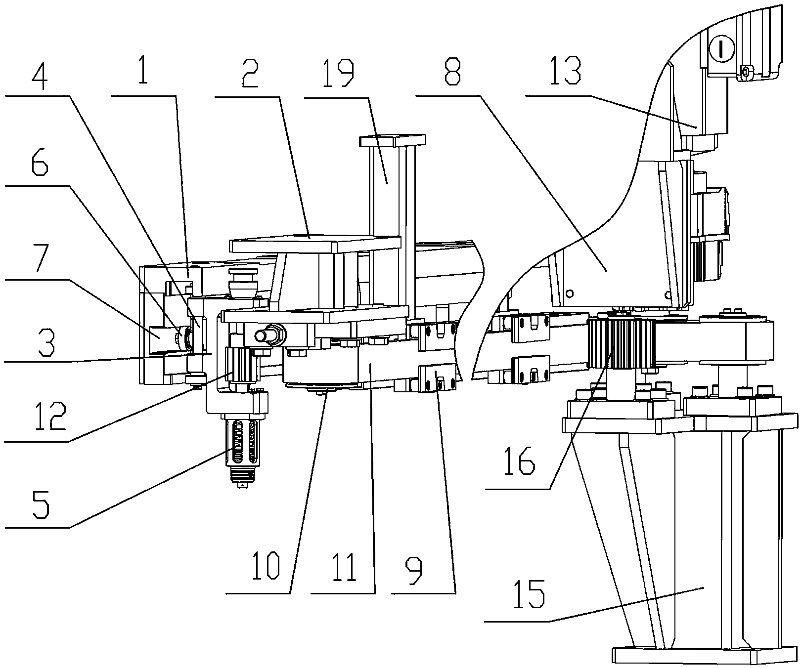
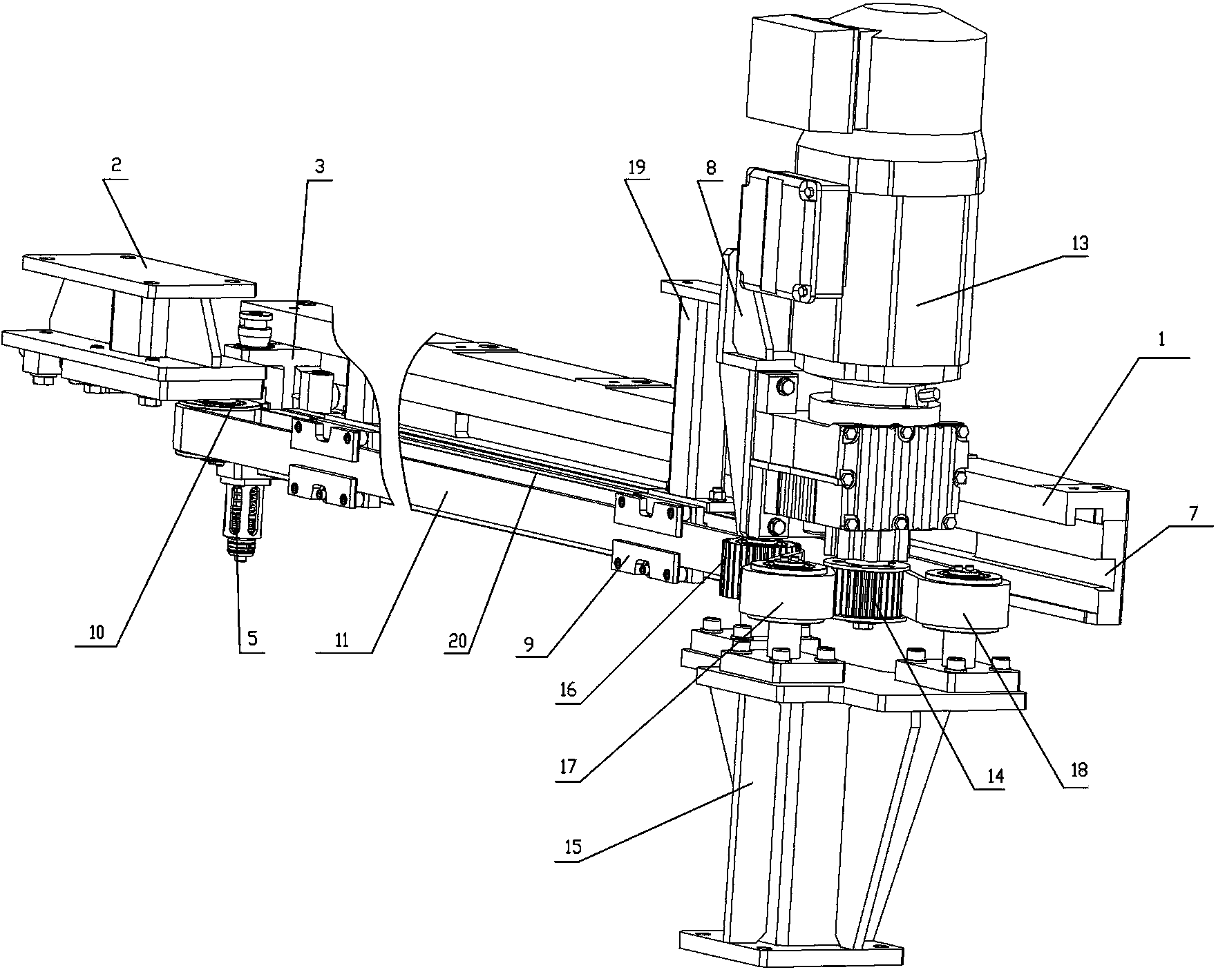
[0007] A warming chain structure such as figure 1 and figure 2 As shown, it includes a guide rail 1 with a guide groove 7 installed horizontally on the heating machine frame, and a transmission wheel support seat 2 installed on the heating machine frame is arranged perpendicular to the direction of the guide rail 1, and the transmission wheel support seat 2 A bracket 3 is set between the guide rail 1, and the rotating shaft 4 runs through the bracket 3 vertically. A manipulator 5 for clamping preforms is installed at the bottom of the rotating shaft 4. A roller 6 is arranged on the side of the bracket 3 facing the guide rail 1, and the roller 6 extends into the guide rail. 1 slides along the guide groove 7, along the direction of the parallel guide rail 1, there is also a drive mechanism support frame 8 installed on the heating machine frame opposite to the drive wheel support seat 2, and the transmission shaft vertically runs through the drive mechanism support frame 8. Its...


PUM


Abstract

The invention discloses a heating chain structure. An idler wheel on a support slides along a guide rail; when a mechanical arm carrying a bottle blank slides to a transmission assembly, a first gear on a rotation shaft is engaged with a toothed belt in the transmission assembly; the bottle blank sequentially moves forward by being carried by the mechanical arm and under the combined action of the first gear and the toothed belt, the rotation shaft can revolve on its own axis and drive the bottle blank to rotate together by the mechanical arm so that the bottle blank can move forward with rotation; a transmission mechanism in the transmission assembly is connected to a driving mechanism by a transmission shaft, and when the driving mechanism operates, the driving mechanism drives the transmission shaft to rotate so that the transmission shaft drives the transmission mechanism to rotate and thus the toothed belt is driven to rotate; and through control on a driving mechanism rate, a toothed belt movement rate can be adjusted so that a rotation rate of the first gear engaged with the toothed belt can be adjusted and rotational velocity of the bottle blank can be further adjusted and thus rotational velocity requirements on different bottle blanks in heating can be satisfied and good quality of later blow-molded bottles is guaranteed.

Description

technical field [0001] The invention relates to a preform heating machine, in particular to a heating chain structure inside the heating machine. Background technique [0002] The preform needs to be preheated by a heating machine before blowing to ensure the quality of the subsequent blow molded bottle. Therefore, whether the preform is heated evenly during the preheating process will affect the quality of the finished bottle. At present, the heating chain structure in the heating machine includes a support and a guide rail with a guide groove installed on the heating machine frame. Oppositely, there is a second sprocket mounted on the bottom of the sprocket support seat, and the chain is sleeved on the first sprocket and the second sprocket at the same time, so that the first sprocket, the second sprocket and the chain are integrated to form a transmission assembly. There is a bracket between the guide rail and the transmission assembly, and a shaft runs through the brac...

Claims


Application Information

Patent Timeline
Patent Type & Authority Applications(China)
IPC IPC(8): B29C49/64B29L22/00
Inventor 邓志军
Owner GUANGZHOU TECH LONG PACKAGING MACHINERY CO LTD
Learn More