
Potential encoding integrated structure

An integrated and coded technology, applied in the direction of resistance elements including multiple resistance elements, resistance elements adjusted by short-circuiting different numbers of resistance elements, etc., to achieve the effect of simple structure, saving electronic equipment space, and reducing the volume of electronic equipment

Inactive Publication Date: 2014-03-12
DONG GUAN CHANG TAI ER ELECTRONICS
View PDF8 Cites 2 Cited by
  • Summary
  • Abstract
  • Description
  • Claims
  • Application Information

AI Technical Summary

Problems solved by technology

[0002] An encoder is an electronic component that compiles and converts signals or data into signal forms that can be used for communication, transmission and storage. It is widely used in the field of electronic communication equipment manufacturing in various industries; a potentiometer is a device that controls resistance. It is also widely used in the field of electronic communication equipment manufacturing in various industries; and it is difficult to find an encoder that can contain two functions in one on the market, which can realize both The encoding function of the encoder can also realize the analog signal output of the potentiometer. Therefore, the market urgently needs a potential encoding integrated structure that can provide conditions for miniaturized electronic equipment, so that the encoder and potentiometer can be unified and reduce production costs. , make more efficient use of limited electronics space

Method used


Image

  • Potential encoding integrated structure
  • Potential encoding integrated structure
  • Potential encoding integrated structure

Examples


Embodiment Construction

[0028] The present invention will be described in further detail below in conjunction with the accompanying drawings and specific embodiments, and the implementation scope of the present invention is not limited thereto.

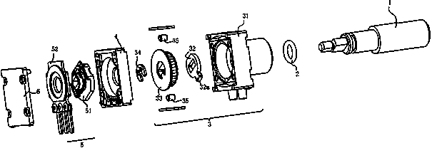
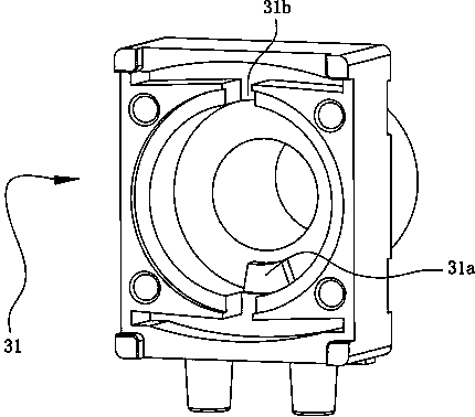
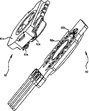
[0029] Such as Figure 1 to Figure 7 As shown, a potential encoding integrated structure 5 described in this embodiment includes a brush plate 51 for conducting electricity, and also includes a resistance carrier 52; one side of the resistance carrier 52 is provided with a conductive ring 52a and Around the plurality of conductive sheets 52b of the conductive ring 52a, the other side of the resistance carrier plate 52 is provided with a plurality of welding holes 52e corresponding to the conductive sheets 52b, and the welding holes 52e are electrically connected to the corresponding conductive sheets 52b. A resistor 52f is electrically connected between two adjacent welding holes 52e, and a first pin 52c and a third pin 52d are provided at the lower end of t...


PUM


Abstract

The invention relates to the technical field encoder parts and particularly relates to a potential encoding integrated structure. The potential encoding integrated structure comprises an electric brush plate and a resistance carrier plate, wherein the electric brush plate is used for conducting electricity; one side of the resistance carrier plate is provided with a conducting ring and a plurality of conducting strips surrounding the conducting ring; the other side of the resistance carrier plate is provided with a plurality of welding holes corresponding to the conducting strips; the welding holes are electrically connected with the corresponding conducting strips; and a resistor is electrically connected between every two adjacent welding holes. Through the arrangement, integration of the encoder and a potentiometer is realized, i.e. the encoder and the potentiometer are combined into one whole body; better conditions are created for saving limited space of electronic equipment and reducing the size of the electronic equipment; the potential encoding integrated structure has a simple structure, is low in cost and provides conditions for integration of the encoder and the potentiometer.

Description

technical field [0001] The invention relates to the technical field of encoder components, in particular to an integrated potential encoding structure. Background technique [0002] An encoder is an electronic component that compiles and converts signals or data into signal forms that can be used for communication, transmission and storage. It is widely used in the field of electronic communication equipment manufacturing in various industries; a potentiometer is a device that controls resistance. It is also widely used in the field of electronic communication equipment manufacturing in various industries; and it is difficult to find an encoder that can contain two functions in one on the market, which can realize both The encoding function of the encoder can also realize the analog signal output of the potentiometer. Therefore, the market urgently needs a potential encoding integrated structure that can provide conditions for miniaturized electronic equipment, so that the e...

Claims


Application Information

Patent Timeline
Patent Type & Authority Applications(China)
IPC IPC(8): H01C10/06H01C10/16
CPCH01C10/06H01C10/16
Inventor 金志良林正生辛文涛杨晓德梁湖勇黄鸿卿廖金华田维金
Owner DONG GUAN CHANG TAI ER ELECTRONICS
Learn More