Filtering device for high-viscosity fluids

A filter device and high viscosity technology, applied in the direction of filtration separation, fixed filter element filter, chemical instrument and method, etc., can solve the problems of flow rate reduction, change, and prolongation of residence time

Active Publication Date: 2014-02-26
NORDSON HLDG S A R L & CO
View PDF7 Cites 4 Cited by
  • Summary
  • Abstract
  • Description
  • Claims
  • Application Information

AI Technical Summary

Problems solved by technology

This modification of the geometry of the flow channel on the discharge side in turn leads to a reduction in the flow velocity and thus to a prolonged residence time of the fluid quantity present in the partial channel, whereby for example in the case of filtration of plastic melts in conjunction with housing heating - start, there is a risk of thermally induced changes

Method used


Image

  • Filtering device for high-viscosity fluids
  • Filtering device for high-viscosity fluids
  • Filtering device for high-viscosity fluids

Examples


Embodiment Construction

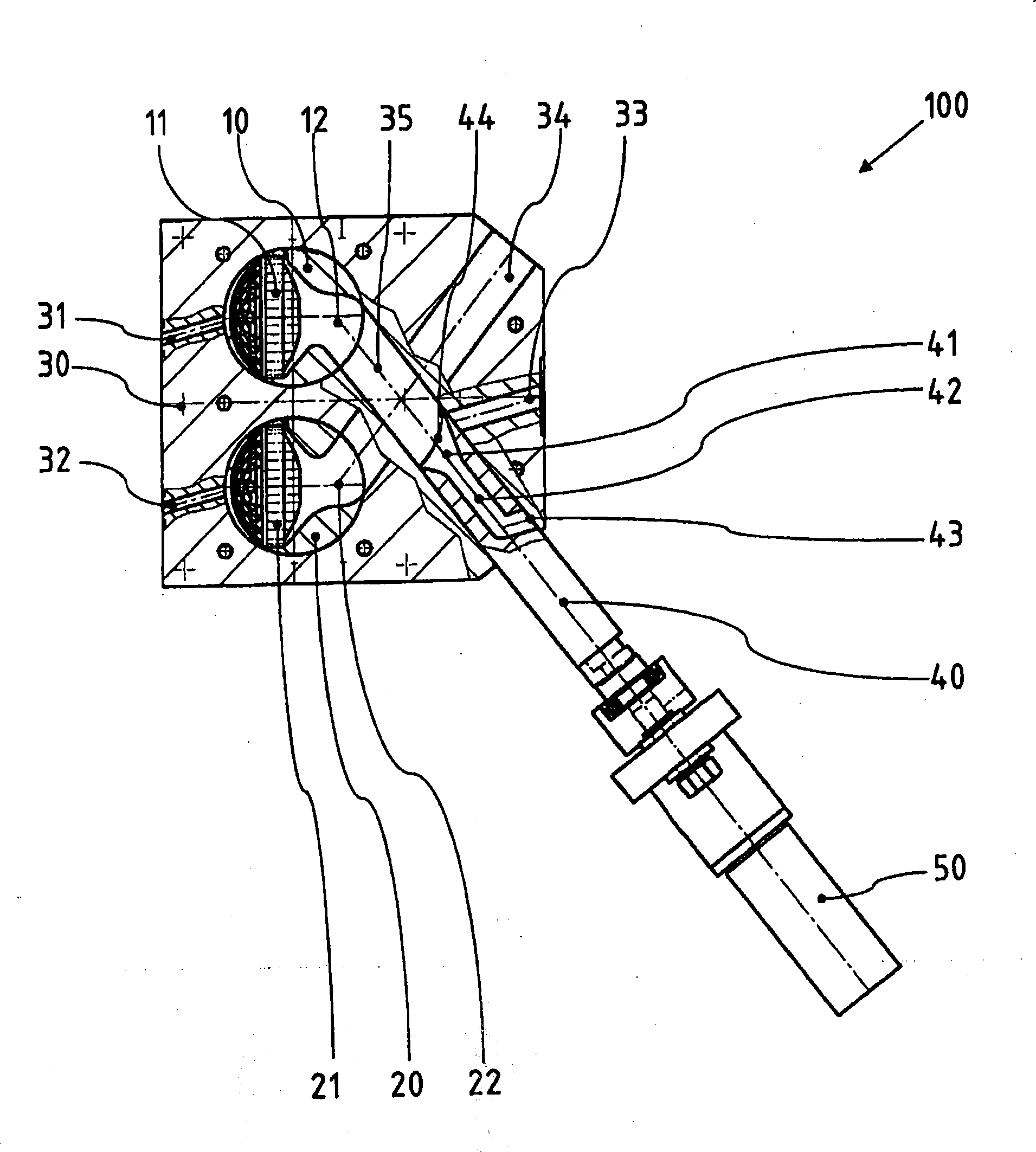
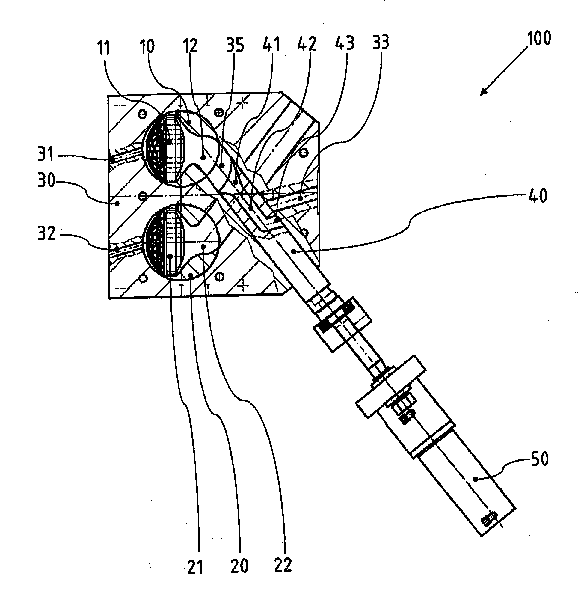
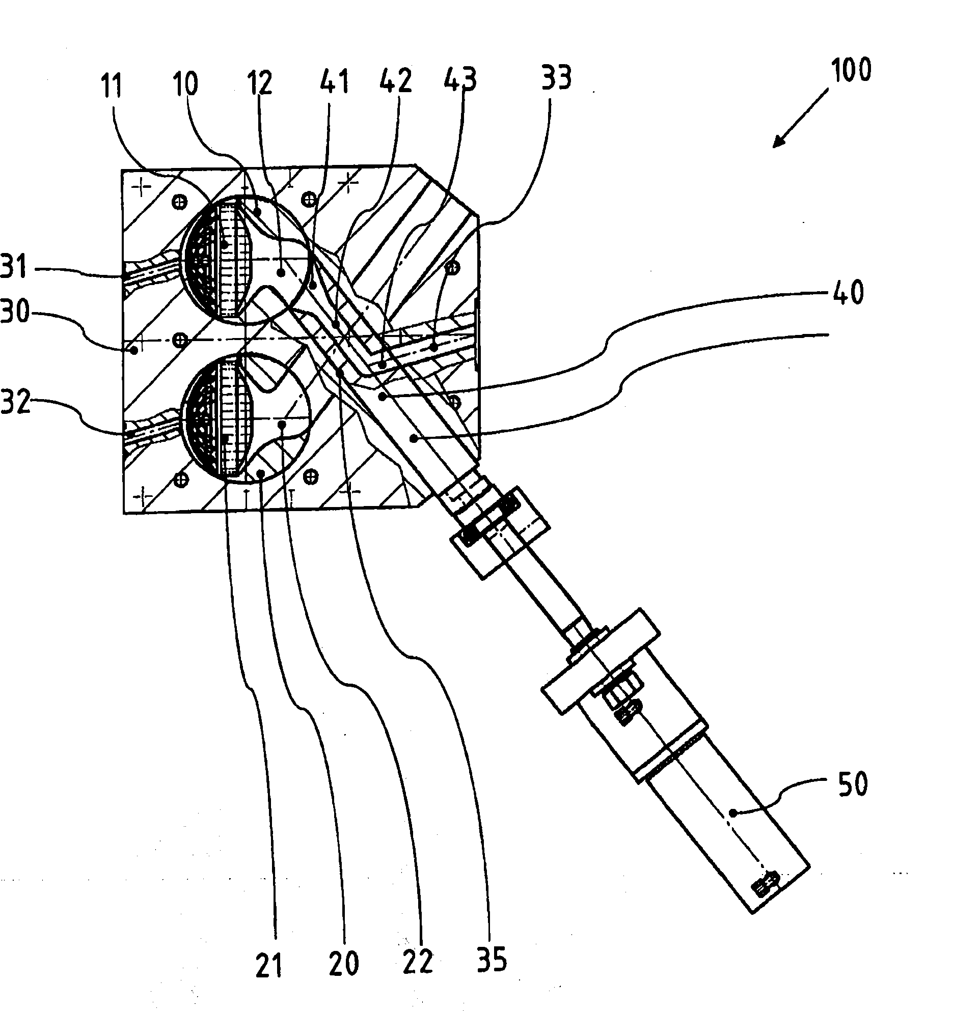
[0035] figure 1Shown is a filter device 100 formed as a screen plug body exchanger, consisting essentially of:

[0036] · Housing 30,

[0037] · Plunger-like screen carrying elements 10, 20, movably supported in housing bores

[0038] · one squeeze piston 40 per screen carrying element, and

[0039] • Drive 50 for extrusion piston 40 .

[0040] Each sieve carrying element 10,20 each has one figure 1 Screen space 12, 22 shown in section. One filter element 11 , 21 is inserted in each case in the screen space.

[0041] When the screen carrying elements 10, 20 are in the backwash position, on the dirt side, i.e. Figures 1 to 3 To the left in each case, the screen spaces 12 , 22 are each connected to a backflush channel 31 , 32 provided in the housing 30 .

[0042] figure 1 The sectional view is arranged so that the partial passages 34, 35 that are originally on the layered planes that are staggered from each other on the real object appear to be on a sectional plane. Th...


PUM


Abstract

The invention relates to a filtering device (100) for high-viscosity fluids, having a partial channel (34) in the housing (30) and a displacing piston (40), which can be inserted into the partial channel (34, 35). The displacing piston (40) comprises at least one inner fluid line (42), which extends from an inlet opening (41) to an outlet opening (43) on the circumference. The outside diameter of the displacing piston (40) corresponds to the inside diameter of the partial channel (34, 35). The displacing piston (40) can be positioned in a production position with the outlet opening (43) of said displacing piston in front of the opening of the discharge channel (33) into the partial channel (34, 35) and can be pulled back to a backflushing initial position within the partial channel (34), wherein along a backflushing displacement path, the opening of the discharge channel (33) into the partial channel (35) is covered by the outer wall of the displacing piston (40) and / or the outlet opening (43) of the displacing piston (40) is covered by the inner wall of the partial channel (34).

Description

technical field [0001] The invention relates to a filter device for highly viscous fluids having the features of the preamble of claim 1 . Background technique [0002] For filtering highly viscous media, for example especially plastic melts, filter devices are known which are designed in the form of so-called screen plunger exchangers. In a construction known, for example, from EP1778379B1, two plunger-shaped screen-carrying elements are arranged displaceably in the housing. Each sieve carrier has at least one sieve point, on which a sieve space is formed in each case. At least one filter element is inserted in each screen space. The feed channel in the housing branches off to the sieve, so that the melt is introduced into the sieve space through a corresponding filter element. Viewed in the direction of flow, partial channels are also provided downstream of the filter element, through which the plastic melt flows away. The partial channels are joined at a point on or i...

Claims


Application Information

Patent Timeline
Patent Type & Authority Applications(China)
IPC IPC(8): B01D29/01B01D29/52B01D29/66B29C48/03B29C48/70B29C48/74
CPCB29C47/0815B29C47/0009B29C47/0886B29C48/70B29C48/273B29C48/362B29C48/705B29C48/2554B29C48/03B29B7/58B01D29/01B01D29/52B01D29/665
Inventor S·韦斯特曼
Owner NORDSON HLDG S A R L & CO
Why Eureka
Try Eureka