Interference objective driving device

A technology of driving device and objective lens, which is applied in the direction of measuring device, optical device, instrument, etc., can solve problems such as unsatisfactory, and achieve the effects of low cost, large displacement range, and reduced damage probability

Active Publication Date: 2014-02-26
SUZHOU UNIV
View PDF4 Cites 3 Cited by
  • Summary
  • Abstract
  • Description
  • Claims
  • Application Information

AI Technical Summary

Problems solved by technology

Therefore, an objective lens driving device is required to drive it, but some existing objective lens driving devices cannot meet the requirements of large micro-displacement output in order to ensure high-precision displacement output.

Method used


Image

  • Interference objective driving device
  • Interference objective driving device

Examples


Embodiment Construction

[0025] In order to enable those skilled in the art to better understand the technical solutions in the present invention, the technical solutions in the embodiments of the present invention will be clearly and completely described below in conjunction with the drawings in the embodiments of the present invention. Obviously, the described The embodiments are only some of the embodiments of the present invention, not all of them. Based on the embodiments of the present invention, all other embodiments obtained by persons of ordinary skill in the art without making creative efforts shall fall within the protection scope of the present invention.

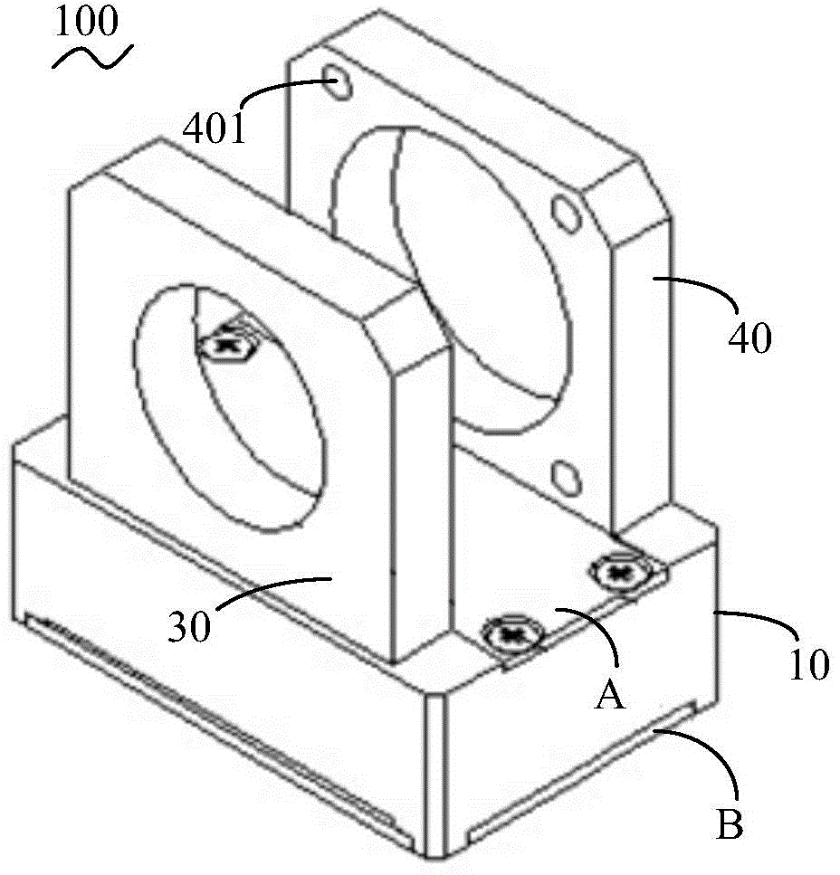
[0026] Such as figure 1 As shown, the interference objective lens driving device 100 of the present invention includes a body 10 on which a through chamber 101 is formed, and the chamber 101 has an upper opening and a lower opening opposite to the upper opening. The upper opening and the lower opening are provided with corresponding up...


PUM


Abstract

The invention discloses an interference objective driving device. The interference objective driving device comprises a body, a mounting rack and a fixing rack. A through chamber is formed in the body, and an amplifying mechanism is arranged in the chamber and comprises arc metal frames arranged oppositely and metal plate frames which are integrally formed with the arc metal frames and arranged oppositely. The metal plate frames are arranged between the arc metal frames and are perpendicular to the arc metal frames. A piezoelectric ceramic element, a pre-tensioning jackscrew and a roll ball are also arranged in the chamber. The piezoelectric ceramic element is integrally connected between the metal plate frames, the pre-tensioning jackscrew is in threaded connection with the body, the roll ball is matched with the pre-tensioning jackscrew, and the roll ball abuts against the wall face of one side, integrally connected with the metal plate frames, of the piezoelectric ceramic element. According to the interference objective driving device, the amplifying mechanism is used for amplifying infinitesimal displacement of the piezoelectric ceramic element, and therefore a larger displacement range is obtained for the interference objective driving device.

Description

technical field [0001] The invention relates to the field of micro-drive applications, in particular to an interference objective lens drive device. Background technique [0002] The surface quality of mechanical parts not only directly affects the performance of parts, but also affects the quality, reliability and life of products. With the rapid development of modern technology, many high-precision products have higher and higher requirements for surface processing quality, and ultra-precision processing technology has become the forefront of modern technology. Ultra-precision detection technology is a high-tech technology developed in parallel with ultra-precision machining technology. Accurate and reliable measurement of the micro-topography of ultra-precision surfaces has become a key problem to be solved in the field of ultra-precision machining. [0003] The interference objective lens is an instrument that uses the principle of light wave interference to detect the ...

Claims


Application Information

Patent Timeline
Patent Type & Authority Applications(China)
IPC IPC(8): G01B11/24
Inventor 钟博文王振华孙立宁金子祺钱哲
Owner SUZHOU UNIV
Why Eureka
Try Eureka