
A New Transformer Turnover Box

A turnover box and transformer technology, applied in the direction of containers, rigid containers, packaging items, etc., can solve the problems of inconvenient storage management, difficulty in optimization, and inability to place them, and improve the degree of freedom in length and space, reduce rotation links, and improve safety. sexual effect

Active Publication Date: 2016-06-08
STATE GRID CORP OF CHINA +2
View PDF6 Cites 0 Cited by
  • Summary
  • Abstract
  • Description
  • Claims
  • Application Information

AI Technical Summary

Problems solved by technology

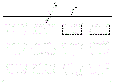
[0002] At present, in the current transformer turnover box used in the automatic detection process, the box body 1 is provided with positioning slots for accommodating current transformers. The positioning slots are arranged in a 3×4 matrix, and the orientation of the transformers 2 in the positioning slots is as follows: figure 1 As shown, but for non-standard large transformers, it cannot be placed due to the extremely small degree of freedom in the turnover box; on the other hand, the existing turnover box height setting is also unreasonable, and the height Unable to match, it brings inconvenience to storage management, difficulty in optimization, and increases the construction cost and operating cost of the automated assembly line system in various links such as warehousing and assembly line

Method used


Image

  • A New Transformer Turnover Box
  • A New Transformer Turnover Box
  • A New Transformer Turnover Box

Examples


Embodiment Construction

[0015] The present invention will be further described below in conjunction with the accompanying drawings. The following examples are only used to illustrate the technical solution of the present invention more clearly, but not to limit the protection scope of the present invention.

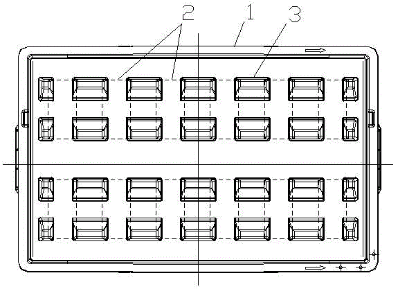
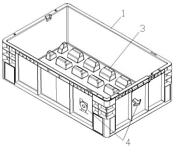
[0016] Such as figure 2 and image 3 As shown, the transformer turnover box of the present invention includes a rectangular box 1 with an upper opening, and the inner bottom of the box 1 is provided with several transformer positioning grooves 3 arranged in an array, and the positioning grooves 3 are arranged in a 2×6 array. And the positioning groove makes the length direction of the current transformer 2 be arranged along the width direction of the turnover box, that is, 6 rows of parallel current transformers are arranged in the length direction of the turnover box, and 2 current transformers are arranged in each row. The length direction of the current transformer runs along the width dir...


PUM


Abstract

The invention discloses a novel transformer turnover box, which comprises a rectangular box body with an upper opening, and a plurality of transformer positioning slots arranged in an array are arranged at the bottom of the box body, and the positioning slots are arranged in a 2×6 array, and the positioning slots use The length direction of the current transformers is arranged along the width direction of the turnover box, and 6 rows of parallel current transformers are arranged in the length direction of the turnover box, and 2 current transformers are arranged in each row, and the length direction of the 2 current transformers is along the turnover box. The width direction of the box runs, and the length direction of the two current transformers is on the same axis. The present invention greatly improves the degree of freedom of the length and space of the current transformer without changing the length and width of the outer profile of the original turnover box, and better solves the problem of placing non-standard large transformers. The transformer placed in this direction is more in line with the operation of the automatic line manipulator, which reduces the rotation link and improves the safety, reliability and efficiency of loading and unloading.

Description

technical field [0001] The invention relates to a novel transformer turnover box, which belongs to the technical field of automatic detection. Background technique [0002] At present, in the current transformer turnover box used in the automatic detection process, the box body 1 is provided with positioning slots for accommodating current transformers. The positioning slots are arranged in a 3×4 matrix, and the orientation of the transformers 2 in the positioning slots is as follows: figure 1 As shown, but for non-standard large transformers, it cannot be placed due to the extremely small degree of freedom in the turnover box; on the other hand, the existing turnover box height setting is also unreasonable, and the height If it cannot be matched, it will cause inconvenience in storage management, difficulty in optimization, and increase the construction cost and operating cost of the automated assembly line system in various links such as warehousing and assembly lines. C...

Claims


Application Information

Patent Timeline
Patent Type & Authority Patents(China)
IPC IPC(8): B65D25/10B65D25/00B65D85/38
Inventor 穆小星蔡奇新黄奇峰
Owner STATE GRID CORP OF CHINA
Learn More