Lying bed

A technology of lying bed and main body, applied in the field of lying bed, can solve the problems such as the adjustment and locking positioning is not firm enough, the angle of the ceiling is not easy, etc., and achieve the effect of simple and reasonable structure, large locking force and increased friction

Inactive Publication Date: 2014-02-26
ZHEJIANG JIAYI IND
View PDF10 Cites 2 Cited by
  • Summary
  • Abstract
  • Description
  • Claims
  • Application Information

AI Technical Summary

Problems solved by technology

[0002] With the improvement of the quality of life, people pay more and more attention to how to arrange their leisure time. On holidays or after get off work, a comfortable bed on the balcony or yard at home becomes an ideal tool for people to relieve fatigue and take a rest. At the same time, in order to avoid direct sunlight or light rain outdoors, a ceiling is generally set above the bed. In the prior art, the angle of the ceiling is not easy to adjust and the locking and positioning are not firm enough.

Method used


Image

  • Lying bed
  • Lying bed
  • Lying bed

Examples


Embodiment 1

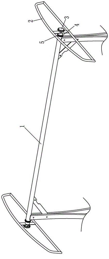
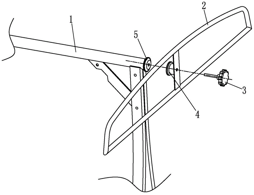
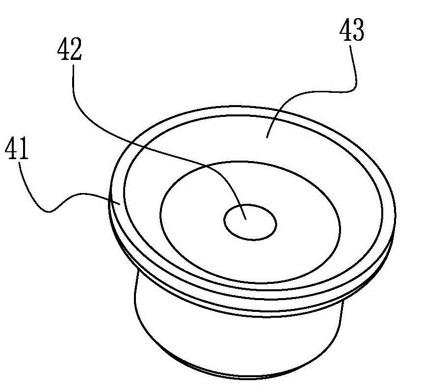
[0013] A kind of lying bed, comprises lying bed main body, and the top of described lying bed main body is horizontally provided with a crossbeam rod 1, as figure 1 , figure 2 As shown, the two ends of the beam rod 1 are installed with the ceiling side frame 2 through the hand wheel 3, the corner device A4 and the corner device B5, and the two ceiling side frames 2 are tightly installed with tarpaulins. Cylinder B, one end of the cylinder B is provided with a flange B51, and the end surface of the flange B51 is provided with a conical truncated cone 54, and the angler A4 is a cylinder A with a central hole A42, and one end of the cylinder A is provided with a flange A41, the end face of the flange A41 is provided with a truncated conical groove 43 matching the truncated conical 54, the corner B5 is circumferentially fixed on the end of the beam rod 1, the ceiling side frame 2 is provided with a through hole, and the handwheel 3 The threaded end passes through the through hol...


PUM


Abstract

The invention discloses a lying bed. The lying bed comprises a lying bed main body. A transverse beam rod is horizontally arranged at the top of the lying bed main body; ceiling side frames are mounted at the two ends of the transverse beam rod by hand wheels, angle turning devices A and angle turning devices B; tarpaulin is mounted on each of the two ceiling side frames in a tightened manner; each angle turning device B is a column body B with a central hole B and a flange B is arranged at one end of each column body B; each angle turning device A is a column body A with a central hole A and a flange A is arranged at one end of each column body A; each angle turning device B is fixedly arranged on one end part of the transverse beam rod in the peripheral direction; through holes are formed in the ceiling side frames; a thread end of each hand wheel sequentially penetrates through the through hole of the corresponding ceiling side frame and the central hole A of the corresponding angle turning device A to be in threaded connection with the central hole B of the corresponding angle turning device B; the end face of the flange A of each angle turning device A is in conical tabletop contact fit with the end face of the flange B of the corresponding angle turning device B. According to the technical scheme, the structure is simple and reasonable, the angle of a ceiling is convenient to adjust and a locking force is great so that the lying bed can be locked and fixed stably.

Description

technical field [0001] The invention belongs to the field of outdoor furniture, in particular to a lying bed. Background technique [0002] With the improvement of the quality of life, people pay more and more attention to how to arrange their leisure time. On holidays or after get off work, a comfortable bed on the balcony or yard at home becomes an ideal tool for people to relieve fatigue and take a rest. Simultaneously, in order to avoid direct sunlight or light rain outdoors, a ceiling is generally arranged above the bed. In the prior art, the angle of the ceiling is not easy to adjust and the locking and positioning are not firm enough. Contents of the invention [0003] In order to solve the above-mentioned technical problems, the object of the present invention is to provide a lying bed with a simple and reasonable structure, convenient adjustment of the ceiling angle, large locking force, and stable locking and fixing. [0004] In order to achieve the above-mention...

Claims


Application Information

Patent Timeline
Patent Type & Authority Applications(China)
IPC IPC(8): A47C17/64A47C17/86E04H15/02
Inventor 李韧刘波高青峰
Owner ZHEJIANG JIAYI IND
Why Eureka
Try Eureka