
Two-degree-of-freedom high-precision large-stroke air-bearing workpiece platform

A high-precision, high-degree-of-freedom technology, applied in the direction of photolithography exposure devices, microlithography exposure equipment, etc., can solve the problems of limited rigidity, large height, unfavorable engineering realization, etc., and achieve lower processing accuracy requirements and high air flotation stiffness , to ensure the effect of the air film unchanged

Inactive Publication Date: 2015-04-22
INST OF OPTICS & ELECTRONICS - CHINESE ACAD OF SCI
View PDF8 Cites 1 Cited by
  • Summary
  • Abstract
  • Description
  • Claims
  • Application Information

AI Technical Summary

Problems solved by technology

However, the two-dimensional motion mechanism of this invention is arranged in layers in space, so the height is large and the center of gravity is high, which is not conducive to the realization of high-precision micro-nano positioning; the driving mechanism uses a screw rod, which has the following problems:
However, the air flotation guide rail of this invention adopts a highly closed rigid structure, which requires high machining accuracy and difficult assembly and adjustment. At the same time, it also adopts bilateral guide rail guidance and high rigidity connection, and also requires very high machining accuracy of the guide rail, base and air flotation unit. Strict, extremely difficult to assemble and adjust, because it is not conducive to the engineering realization of the invention
[0006] Patent CN201010508109.8 discloses an air-floating pad and an air-floating guide rail assembled from the air-floating pad. This invention solves the problem that the air film changes due to the parallelism error of the guide rails, but the air-floating stiffness of the air-floating pad is actually Determined by the pressure chamber, due to the compressibility of the air, its stiffness is limited, and it is not suitable for the main guide rail;
[0007] The air-floating guide rail disclosed in patent CN201010508116.8 is essentially a highly rigid closed air-floating structure, which requires high processing precision; in addition, the invention also divides the usually integral air-floating block into several small pieces, which also increases Increased processing difficulty, which is not conducive to engineering realization and product development

Method used


Image

  • Two-degree-of-freedom high-precision large-stroke air-bearing workpiece platform
  • Two-degree-of-freedom high-precision large-stroke air-bearing workpiece platform
  • Two-degree-of-freedom high-precision large-stroke air-bearing workpiece platform

Examples


Embodiment Construction

[0042] In order to make the above objects, features and advantages of the present invention more obvious and understandable, the specific implementation of the present invention will be described in detail below.

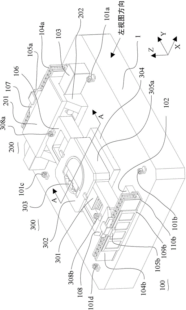
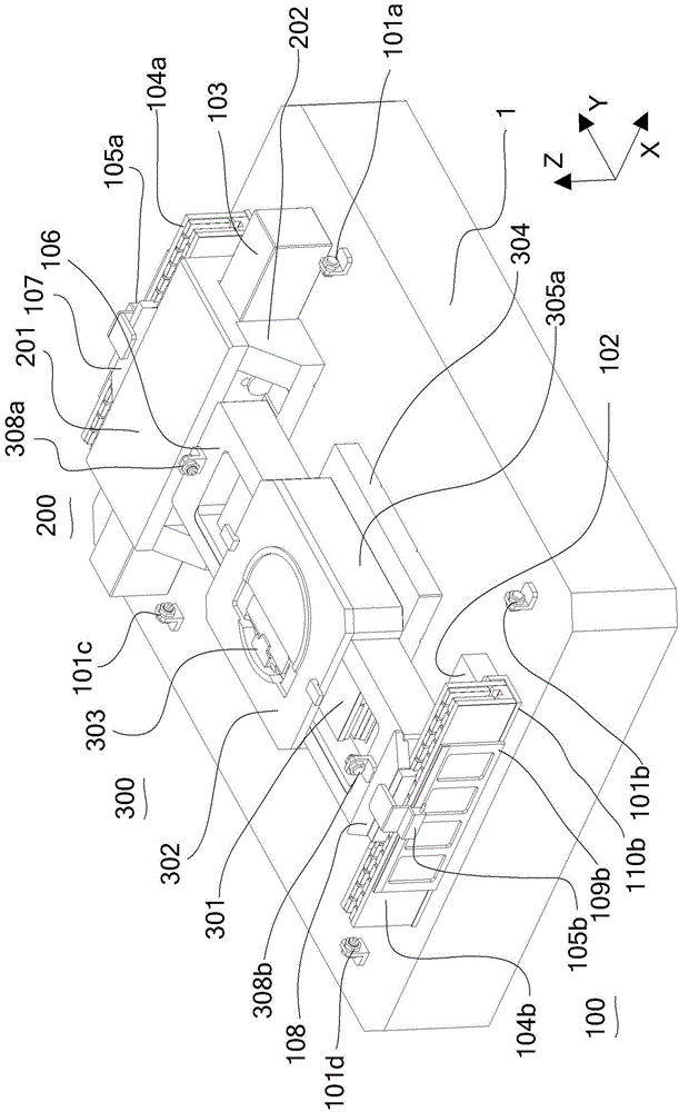
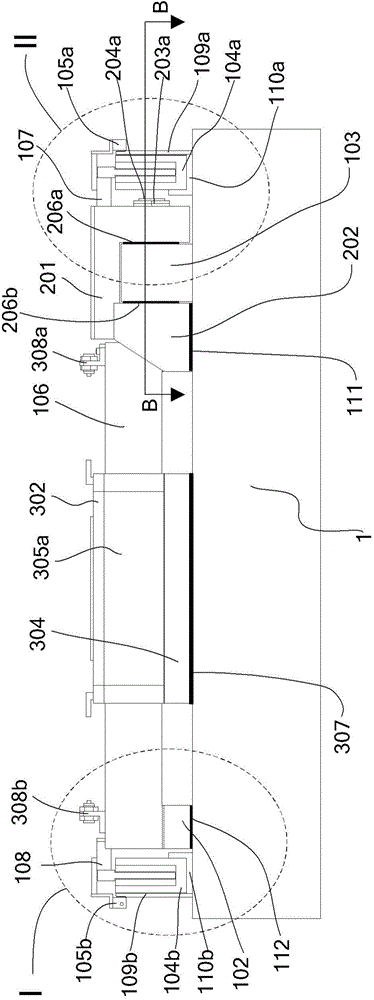
[0043] Such as Figure 1a , Figure 1b As shown, the two-degree-of-freedom high-precision large-stroke air-floating workpiece table of the present invention is composed of a marble base 1 , an X-direction motion table 100 and a Y-direction motion table 300 . The marble base 1 is located at the bottom of the X-direction motion table 100 and the Y-direction motion table 300, and is used to support the entire X-direction motion table 100 and the Y-direction motion table 300; the Y-direction motion table 300 is erected on the X-direction motion table 100, and the Y direction The motion table 300 and the X-direction motion table 100 are coupled through the X beam 106 to complete the transmission of the X-direction motion to the Y-direction motion table, so that the workp...


PUM


Abstract

The invention discloses a two-degree-of-freedom high-precision large-stroke air-bearing workpiece platform, comprising a marble base, an X-direction motion bench and a Y-direction motion bench, wherein the marble base is located at the bottoms of the X-direction motion bench and the Y-direction motion bench and used for supporting the whole X-direction motion bench and the whole Y-direction motion bench, the Y-direction motion bench is erected on the X-direction motion bench, and the Y-direction motion bench and the X-direction motion bench are coupled through the X crossbeam of the X-direction motion bench so as to realize transfer of X-direction motion to the Y-direction motion bench, which enables the workpiece platform to have an X-Y two-degree-of-freedom motion function. According to the invention, the Y-direction motion bench is erected on the X-direction motion bench, thereby forming the H-shaped two-degree-of-freedom high-precision large-stroke air-bearing workpiece platform; linear motor driving and friction-free air-bearing guide rail guiding are employed by the workpiece platform, so the platform can realize high-speed and large-stroke motion and high-precision positioning.

Description

technical field [0001] The invention relates to the technical field of a two-degree-of-freedom large-stroke high-precision positioning platform used in the field of lithography, in particular to a two-degree-of-freedom high-precision large-stroke air-floating workpiece table, which can realize two degrees of freedom in X and Y directions. Motion platform with stroke drive and high precision positioning. Background technique [0002] Patent CN201110438625.2 discloses a two-dimensional air-floating motion table, the driving mechanism is composed of a rotating motor + screw rod, and the guide rail is composed of an air-floating guide rail. However, the two-dimensional motion mechanism of this invention is arranged in layers in space, so the height is large and the center of gravity is high, which is not conducive to the realization of high-precision micro-nano positioning; the driving mechanism uses a screw rod, which has the following problems: [0003] a) It is difficult to ...

Claims


Application Information

Patent Timeline
Patent Type & Authority Patents(China)
IPC IPC(8): G03F7/20
Inventor 周清华
Owner INST OF OPTICS & ELECTRONICS - CHINESE ACAD OF SCI
Learn More