
On-line monitoring device for lightning current of overhead transmission line

A technology for overhead transmission lines and monitoring devices, which is applied in the direction of measurement using digital measurement technology, which can solve problems such as different lightning protection effects, power grid loss, and high cost, and achieve the effects of ensuring long-term normal work, increasing use time, and reducing capacity.

Inactive Publication Date: 2014-02-19
STATE GRID CORP OF CHINA +1
View PDF9 Cites 12 Cited by
  • Summary
  • Abstract
  • Description
  • Claims
  • Application Information

AI Technical Summary

Problems solved by technology

[0002] Lightning accidents on transmission lines bring huge losses to the power grid every year. Among 10kV-35kV equipment accidents, the proportion of lightning tripping times accounts for the first in the total number of tripping times of power transmission and distribution equipment, and the proportion of unplanned outages of power transmission and distribution equipment accounts for a large proportion. The second place has seriously affected the safe and reliable operation of the power grid
Due to the uncertainty of lightning current amplitude and direction, the same lightning protection system has different protection effects for different lightning strikes, and it is difficult to find the lightning strike fault point
Previous lightning current detection devices, such as Chinese patent CN201087843Y "a lightning current detection device", cannot locate the time and amplitude of lightning strikes, let alone measure the lightning current waveform; Chinese patent CN101937015A "a lightning current and "On-line monitoring device for lightning voltage waveform parameters" needs to be installed on each wire, and the cost is high. Its technical route and the adoption of components are different from those of the present invention.

Method used


Image

  • On-line monitoring device for lightning current of overhead transmission line
  • On-line monitoring device for lightning current of overhead transmission line

Examples


Embodiment Construction

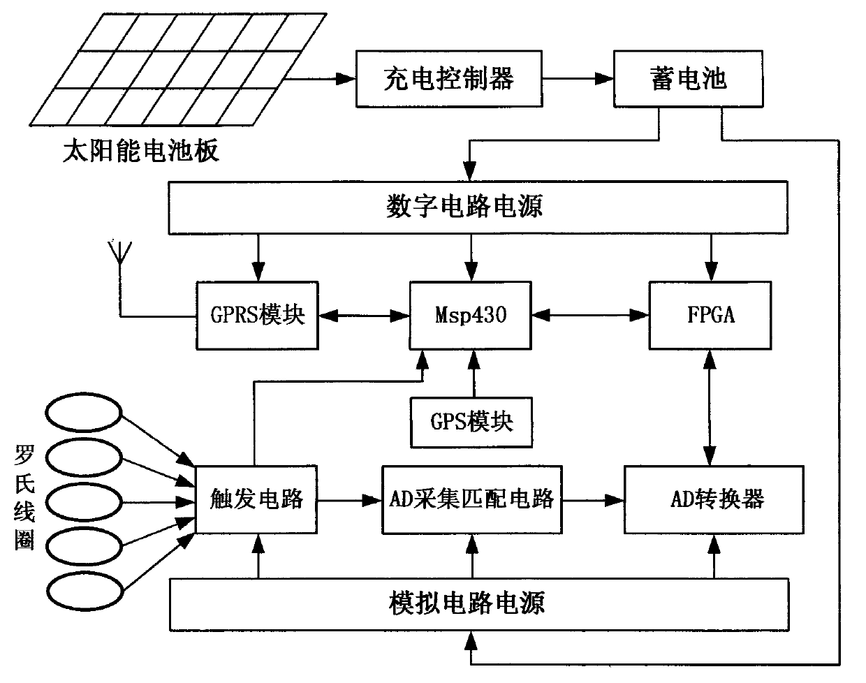
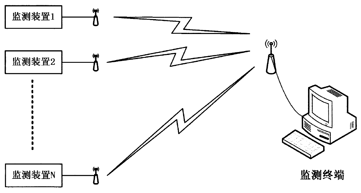
[0014] attached figure 1 It is a schematic structural diagram of the lightning current online monitoring device for overhead transmission lines in this embodiment, with figure 2 It is a schematic diagram of a system composed of a control center terminal computer and multiple monitoring devices. The device consists of Msp430 single-chip microcomputer, FPGA field programmable gate array, trigger circuit, AD acquisition matching circuit, AD converter, GPS module, GPRS communication module, solar panel, charge controller, battery, Rogowski coil, digital circuit power supply, analog Composed of circuit power supply components, the Rogowski coil set on the transmission line tower insulator string and the tower lightning protection line is connected to the trigger circuit, the trigger circuit is connected to the Msp430 single-chip microcomputer, AD acquisition matching circuit, and the analog circuit power supply, and the Msp430 single-chip microcomputer communicates with the GPS mo...


PUM


Abstract

An on-line monitoring device for lightning current of an overhead transmission line is composed of an Msp430 single chip microcomputer, an FPGA, a trigger circuit, an AD collection and matching circuit, an AD converter, a GPS module, a GPRS communication module, a solar panel, a charge controller, a storage battery, Rogowski coils, a digit circuit power supply and an analog circuit power supply, is installed at a cross arm of a pole tower, and is powered by solar batteries, and sensors are installed on an insulator chain of the pole tower of the power transmission line and a lightning conductor of the pole tower. When a placed near a monitored point is struck by lightning, the Rogowski coils output induction voltage. When the voltage reaches a certain threshold value, the trigger circuit of the device starts to collect lightning current signals, and sends a measurement result to a terminal computer through a wireless communication method. A lightning current oscillogram and waveform parameters of each path are obtained through comprehensive analysis of the terminal computer, and the pole tower is guided to carry out maintenance work.

Description

technical field [0001] The invention relates to a lightning current measuring device for a power transmission line and a lightning protection line. Background technique [0002] Lightning accidents on transmission lines bring huge losses to the power grid every year. Among 10kV-35kV equipment accidents, the proportion of lightning tripping times accounts for the first in the total number of tripping times of power transmission and distribution equipment, and the proportion of unplanned outages of power transmission and distribution equipment accounts for a large proportion. Second, it has seriously affected the safe and reliable operation of the power grid. Due to the uncertainty of the magnitude and direction of the lightning strike current, the same lightning protection system has different protection effects on different lightning strikes, and it is difficult to find the lightning strike fault point. Previous lightning current detection devices, such as Chinese patent CN...

Claims


Application Information

Patent Timeline
IPC IPC(8): G01R19/25
Inventor 赵燕君陈建杰钱江武永国
Owner STATE GRID CORP OF CHINA
Learn More