Method for monitoring machine with rotating shaft

A technology for machines and rotating parts, applied in the direction of machines/engines, instruments, mechanical equipment, etc., can solve problems such as inability to monitor bearings, impossible to distinguish friction points, etc., to achieve the effect of simple installation

Active Publication Date: 2014-02-12
ANSALDO ENERGIA IP UK LTD
View PDF9 Cites 5 Cited by
  • Summary
  • Abstract
  • Description
  • Claims
  • Application Information

AI Technical Summary

Problems solved by technology

[0009] b) The disadvantage is also that it is not possible to distinguish the point of friction between rows of blades with the same number of blades
Furthermore, such systems only allow monitoring of turbines and, in contrast, do not monitor bearings

Method used


Image

  • Method for monitoring machine with rotating shaft
  • Method for monitoring machine with rotating shaft
  • Method for monitoring machine with rotating shaft

Examples


Embodiment Construction

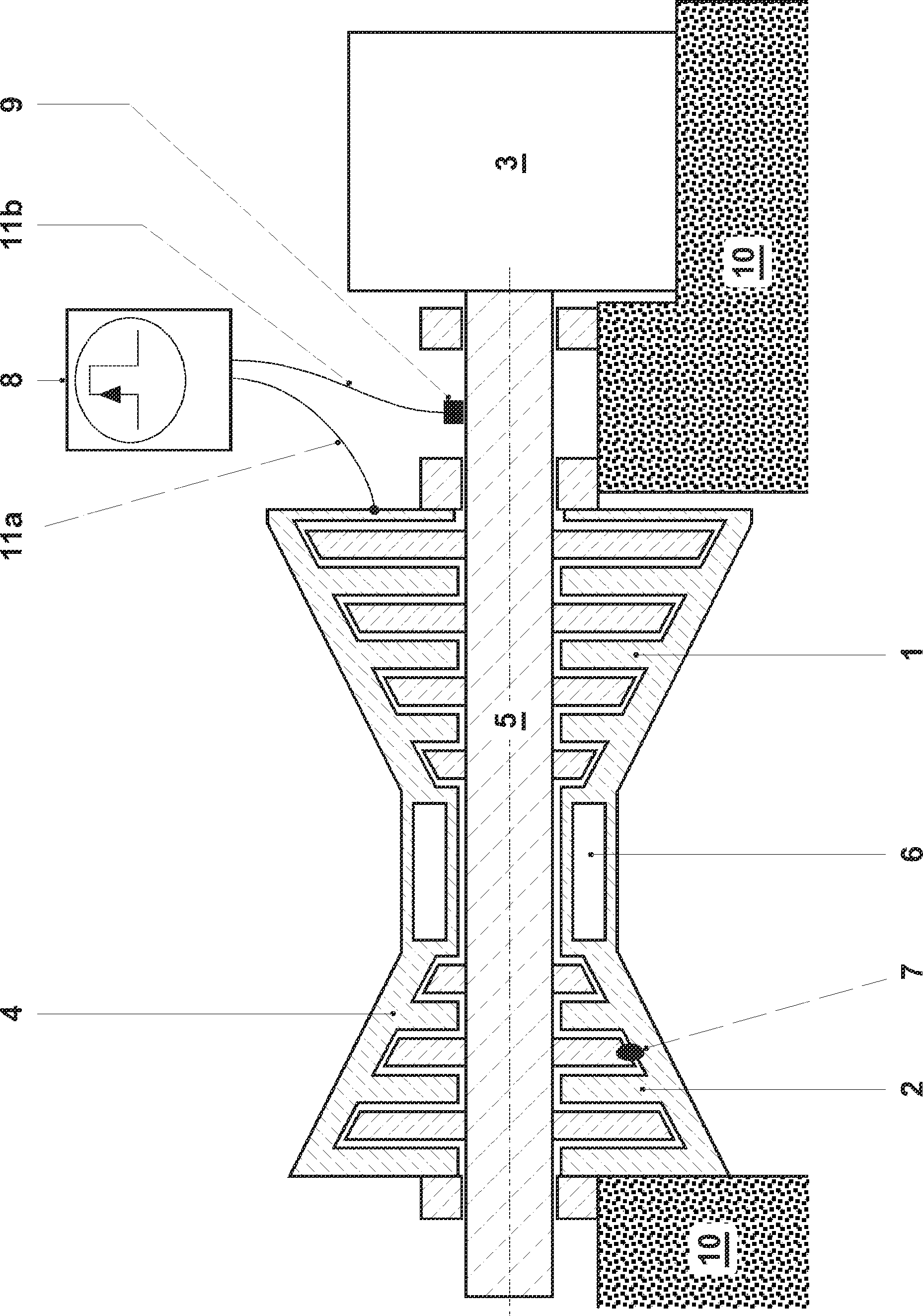
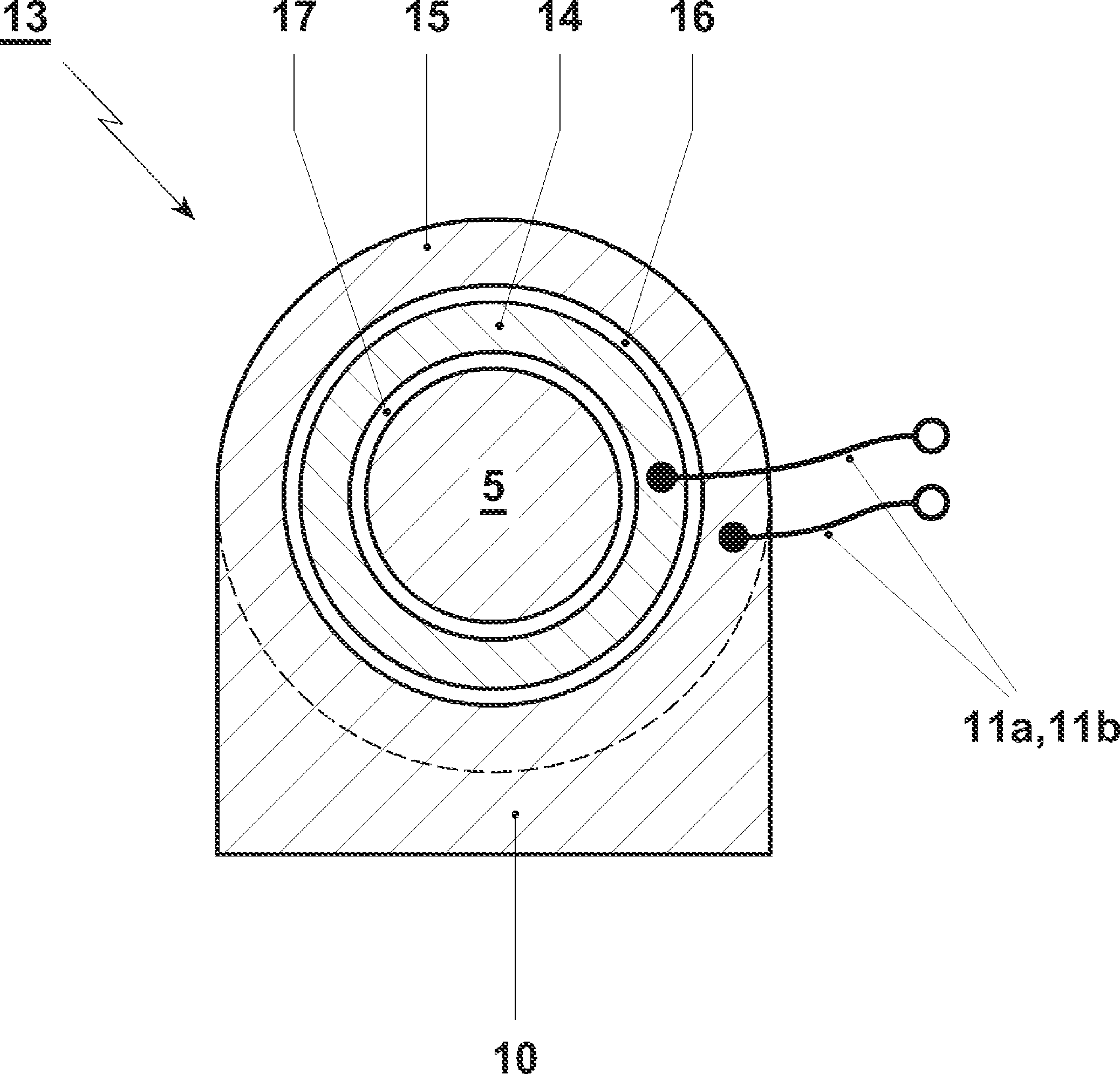
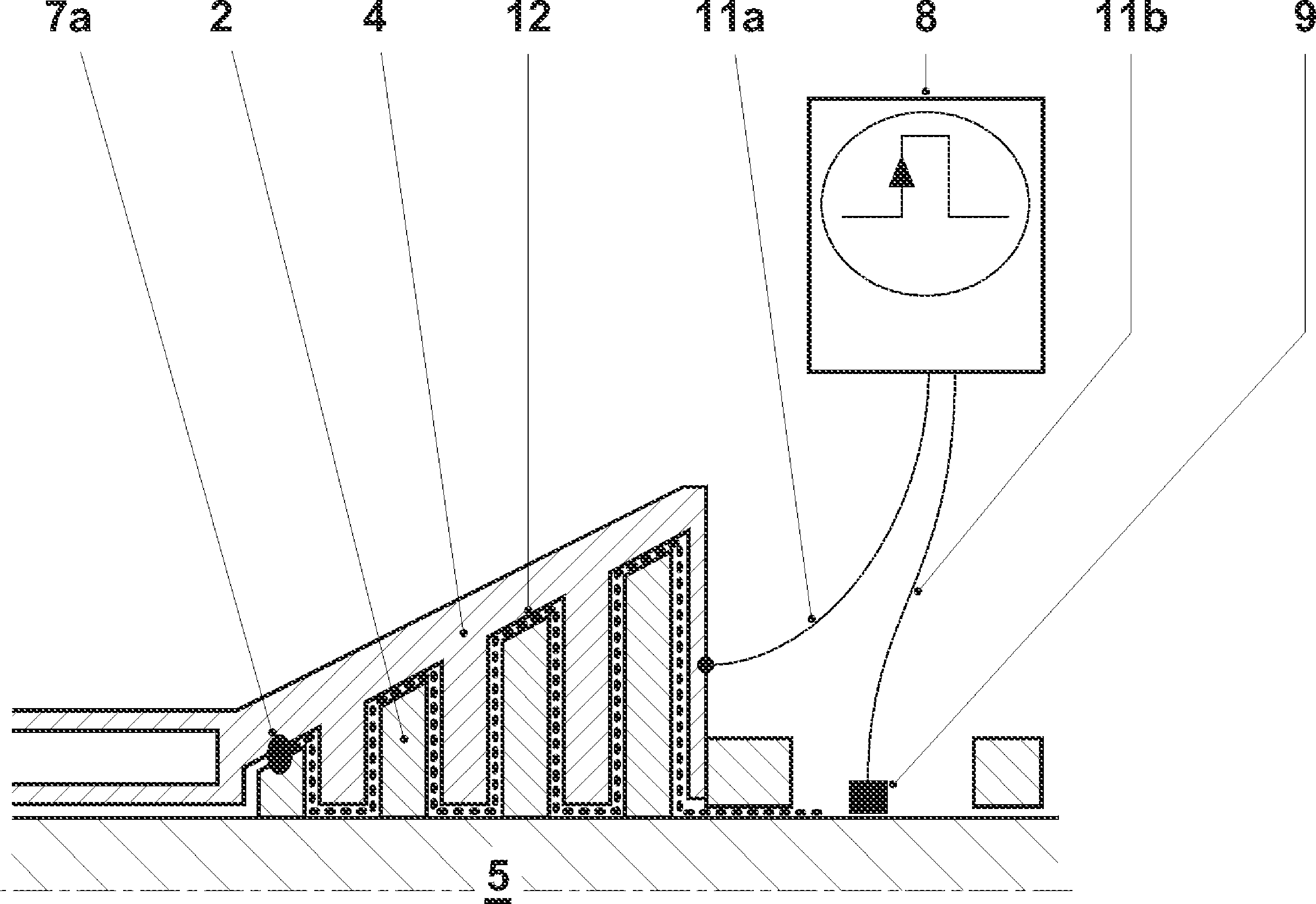
[0037] figure 1A gas turbine train is schematically shown in sectional view in , which essentially consists of at least one compressor 1 , a combustion chamber 6 which is only implied in the figure, a turbine 2 and a generator 3 . Such a group of gas turbines may also be operated by sequential combustion, wherein a first turbine is arranged on the outlet side of a first combustion chamber connected downstream of the compressor, and a second combustion chamber is operated at the outlet side of the first turbine, the combustion The hot gases of the chamber are applied to the second turbine. The point of friction in the turbine is marked as point 7 in the diagram. The measuring device 8 injects said voltage pulses into the coaxial system via the measuring cables 11a, 11b, the contacts on the housing 4 and the shaft contacts 9 and uses these pulses to measure the elapsed time or the transmission characteristic. The always present ground contact is advantageously used as shaft co...


PUM


Abstract

The invention relates to a method for detecting rubbing and/or contact points on machines with rotating parts. The rotating parts form an electrical coaxial system with respect to the stationary parts of such a machine, in which system electrical voltage pulses are propagated at a characteristic speed because of the small distance between the rotating and the stationary part. Short electrical voltage pulses and/or continuous alternating voltage signals are applied between the rotating part and the stationary part, an electrical connection occurring between the rotating and the stationary part at a rubbing and/or contact point. In order to locate this rubbing and/or contact point as a point of electrical discontinuity, the period of time until the reflected pulses arrive is measured along the path of propagation of the electrical voltage pulses and/or of the continuous alternating voltage signals.

Description

technical field [0001] The present invention relates to a method for monitoring a machine with a shaft that rotates in operation. The invention also relates to a device for monitoring a machine with a shaft that rotates during operation. [0002] This monitoring relates in particular to generators, turbines and motors in operation and mainly consists in locating the points of friction of the rotor or shaft with the housing which occur when there is friction between the shafts. The main application is the monitoring of gas or steam turbines in large power plant turbine generator banks for this purpose. Background technique [0003] It is known from the prior art to measure the electrical insulation between the rotor or the shaft and the machine housing. This insulation is usually lost when a rubbing point occurs because metal-to-metal contact occurs at the rubbing point. Insulation is easily monitored using a test voltage. Monitoring devices of this type are commercially ...

Claims


Application Information

Patent Timeline
Patent Type & Authority Applications(China)
IPC IPC(8): G01R31/34G01S13/06F02C3/04F01K11/02
CPCG01M15/14
Inventor M.霍贝斯伯格K.Y.哈夫纳E.L.拉濑斯P.布罗奇
Owner ANSALDO ENERGIA IP UK LTD
Why Eureka
Try Eureka