air conditioner

A technology for air conditioners and indoor units, applied in air conditioning systems, space heating and ventilation, space heating and ventilation details, etc., can solve problems such as the inability to stably reduce the wind speed distribution, achieve small performance deviations, reduce unsatisfactory Equalizes and prevents heat transfer performance from deteriorating

Inactive Publication Date: 2016-03-02
HITACHI JOHNSON CONTROLS AIR CONDITIONING INC
View PDF4 Cites 0 Cited by
  • Summary
  • Abstract
  • Description
  • Claims
  • Application Information

AI Technical Summary

Problems solved by technology

[0009] However, decreasing Figure 10 In the above method of unbalanced wind speed distribution, there is a problem that the wind speed distribution cannot be stably reduced when the arrangement pitch of the fins of the back side auxiliary heat exchanger 122 is changed due to manufacturing variations.

Method used


Image

  • air conditioner
  • air conditioner
  • air conditioner

Examples


no. 1 approach

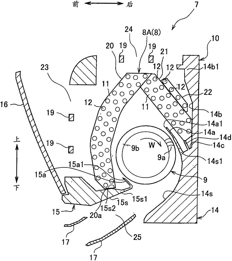
[0035] image 3 It is a side sectional view showing the indoor unit used in the air conditioner of the first embodiment, Figure 4 It is an enlarged side cross-sectional view showing the details of the positional relationship between the back side heat exchanger and the tank of the first embodiment.

[0036] like image 3 As shown, the indoor unit 7 is composed of an indoor heat exchanger 8A, a cross-flow fan 9, a box 10 and the like.

[0037] The housing 10 is provided with an air inlet 23 on the front surface, an air inlet 24 on the upper surface, and an air outlet 25 on the lower part. In addition, a cross-flow fan 9 is disposed in the housing 10 , and a cross-fin tube-type indoor heat exchanger 8A is disposed in the middle of the air passage from the air inlets 23 and 24 to the cross-flow fan 9 . in addition, image 3 The shown reference numeral 19 denotes a housing of an air filter (not shown).

[0038] The indoor heat exchanger 8A is composed of a front heat exchang...

no. 2 approach )

[0065] Figure 6 It is a side sectional view showing the indoor unit used in the air conditioner of the second embodiment, Figure 7 This is an enlarged view showing the details of the positional relationship between the rear side heat exchanger and the tank in the second embodiment. Figure 6 A side sectional view of a part of .

[0066] like Figure 6 As shown, the second embodiment is a form using an indoor heat exchanger 8B instead of the indoor heat exchanger 8A of the first embodiment. About the same structure as 1st Embodiment, the same code|symbol is attached|subjected, and overlapping description is abbreviate|omitted. The indoor heat exchanger 8B is composed of a front side heat exchanger 20 and a back side heat exchanger 31 .

[0067] like Figure 7 As shown, the rear side heat exchanger 31 has a first heat exchange section 31A in which the number of heat transfer tubes 12 arranged in four rows in the air flow direction (arrow A, arrangement direction) and a le...


PUM


Abstract

The invention provides an air conditioner which can reduce imbalance of wind speed distribution in a heat exchanger, avoid reduction of heat exchange performance or increase of noise and has smaller performance deviation. The distance from the lower edge part (22a1) of a back side auxiliary heat exchanger (22) along the orthorhombic direction relative to the arrangement of a heat transfer pipe (12) to a flow path wall surface (14b) is set to be L1, a shortest distance between the back side auxiliary heat exchanger (22) and the flow path wall surface (14b) is set to be L2, and the distance between a back side main heat transfer device (21) and the front end (14a1) of a back nose part (14a) is set to be L3, meeting 0.4< (L2 / L1)<0.6, and 0.55<(L3 / L1).

Description

technical field [0001] The present invention relates to air conditioners. Background technique [0002] Conventional air conditioners include, for example, the technique disclosed in Patent Document 1 as an example of a side cross section of an indoor unit. In this invention, a heat exchanger is arranged in an approximately inverted V shape around the cross-flow fan, and the heat exchanger on the back side is a heat exchanger in which the number of heat transfer tubes arranged in two rows in the air flow direction (hereinafter Referred to as the main heat exchanger on the back side), and a heat exchanger in which the number of heat transfer tubes in the air flow direction is arranged in one row (hereinafter referred to as the auxiliary heat exchanger on the back side). [0003] prior art literature [0004] Patent Document 1: Japanese Patent Laid-Open No. 2009-127875 ( figure 2 ) [0005] However, in the air conditioner described in Patent Document 1, since the back side...

Claims


Application Information

Patent Timeline
Patent Type & Authority Patents(China)
IPC IPC(8): F24F1/00F24F13/30F24F13/24
Inventor 米田广关谷祯夫山崎洋
Owner HITACHI JOHNSON CONTROLS AIR CONDITIONING INC
Why Eureka
Try Eureka