Method and safety concept for recognizing defects in a drive system of a motor vehicle

A technology for driving systems and motor vehicles, applied in motor vehicles, brake control systems, brake safety systems, etc., can solve problems such as high application costs

Active Publication Date: 2014-02-05
BAYERISCHE MOTOREN WERKE AG
View PDF9 Cites 5 Cited by
  • Summary
  • Abstract
  • Description
  • Claims
  • Application Information

AI Technical Summary

Problems solved by technology

resulting in high application overhead

Method used


Image

  • Method and safety concept for recognizing defects in a drive system of a motor vehicle

Examples


Embodiment Construction

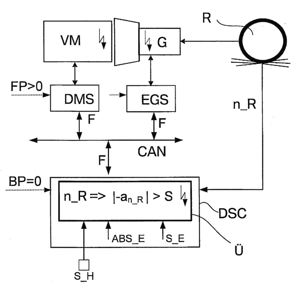
[0036]In the drawing, an embodiment of the invention is shown. The figure shows a schematic overview of the components of a motor vehicle with a possible network of electronically controlled systems including an internal combustion engine VM with an electronic engine control device DMS, a motor vehicle with an electronic transmission control device EGS Automatic transmission G and braking system with Electronic Brake Control DSC. Furthermore, a wheel R of the vehicle is shown schematically in outline, which has a sensor for detecting the wheel speed n_R. The signal for detecting the wheel speed n_R is detected and evaluated in the brake control system DSC. Thus, for example, an acceleration -a which is determined by the rotational speed of the wheels, here in particular negative, is calculated n_R . The communication of the control units DMS, EGS and DSC takes place, for example, via the digital bus connection CAN. The electronic engine control unit DMS also receives, for ...


PUM


Abstract

The invention relates to a method and safety concept for recognizing defects in a drive system of a motor vehicle having an electronically controllable brake regulation system and having at least one electronically controllable drive motor and / or having an electronically controllable clutch and / or having an electronically controllable transmission, wherein an electronic brake control device is allocated to the brake regulation system and is connected to an independent monitoring module, wherein the independent monitoring module verifies the occurrence of an implausible braking torque in order to recognize a defect in the drive system.

Description

technical field [0001] The invention relates to a method and a safety concept for detecting faults in a drive system of a motor vehicle. Background technique [0002] Motor vehicle manufacturers have been required for several years to have self-diagnostic capabilities in electronic control devices or electronic control systems such as digital engine controls or adaptive transmission controls in motor vehicles due to legally prescribed standards (such as ISO or CARB standard specifications) . From this, for example so-called OBD (On-Board Diagnostics) systems have been developed. An example of the construction of an OBD system can be found in the applicant's patent document DE 197 31 283 A1. [0003] In addition to the software scope of the actual function control, the electronic control unit within the motor vehicle has a large software scope for self-diagnosis. An example of self-diagnosis within a control unit is described in the applicant's patent document DE 196 12 85...

Claims


Application Information

Patent Timeline
Patent Type & Authority Applications(China)
IPC IPC(8): B60T8/88B60W50/02
CPCB60T8/885B60W50/029B60W2520/26B60W2520/28B60W2520/105B60T2270/406B60W20/50B60K6/48B60W50/0205B60T2201/09Y02T10/6221B60T2270/413Y02T10/62B60T17/22G07C5/0808
Inventor J·默尔曼R·科斯费尔德H·施托尔茨F·奥斯特雷彻尔C·约翰K-J·胡贝尔H·斯马克曼M·施耐德H·雅各布
Owner BAYERISCHE MOTOREN WERKE AG
Why Eureka
Try Eureka