
Hooking test device of location grids of reactor fuel assembly

A fuel assembly and spacer grid technology is applied in the field of reactor fuel assembly spacer grid out-of-core test devices, and can solve the problems of spacer grid damage, affecting the economy of nuclear power plants, affecting the safety of nuclear power plants, and the like, and reducing the impact. Effect

Active Publication Date: 2014-02-05
NUCLEAR POWER INSTITUTE OF CHINA
View PDF5 Cites 7 Cited by
  • Summary
  • Abstract
  • Description
  • Claims
  • Application Information

AI Technical Summary

Problems solved by technology

During the loading and refueling process of existing nuclear power plant reactor fuel assemblies, adjacent fuel assembly positioning grids were damaged due to mutual hooking. After the hooking occurred, the fuel assembly positioning grids were damaged, and the assembly could no longer be used directly. , not only affects the economics of the nuclear power plant, but also affects the safety of the nuclear power plant operation when the positioning grid is damaged but not found. Therefore, the anti-hook performance of the fuel assembly positioning grid is directly related to the reliability of component stacking and refueling. The operability and structural integrity of the fuel assembly are of paramount importance to the safety of the fuel assembly
[0003] At present, there is no research on the hooking test of the fuel assembly positioning grid in China, so there is no such test device in China. During the development of the fuel assembly in France, the hooking test of the positioning grid has been carried out. The device used is based on the material Some auxiliary devices are added to the testing machine. There is no special test device specially designed for the hook test of the positioning grid, and the French test device cannot measure the lateral preload force between the two grids, set and measure the included angle, and the two grids. Angle setting between racks

Method used


Image

  • Hooking test device of location grids of reactor fuel assembly

Examples


Embodiment

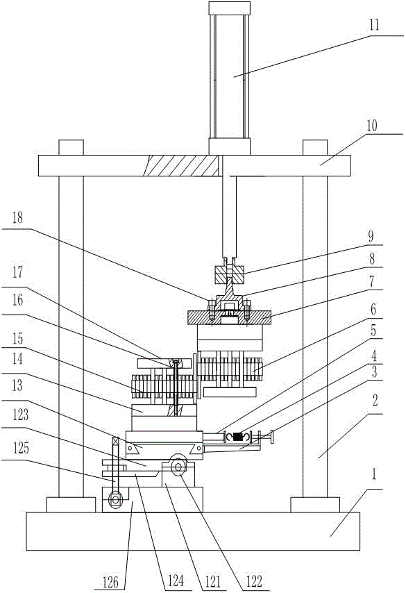
[0023] Such as figure 1As shown, a hooking test device for a reactor fuel assembly positioning grid of the present invention includes a frame bottom plate 1, and the frame bottom plate 1 is fixed on a plane. As an experimental platform, a column 2 is arranged on the frame bottom plate 1, The column 2 is used as the supporting part of the upper gravity, and is also a guide mechanism for adjusting the upper and lower positions of the frame top plate 10. A horizontal base plate 126 is installed on the frame bottom plate 1, and a bearing seat 121 is installed on the horizontal base plate 126. Bearing 122 is installed, and bearing 122 is connected with bearing pressure plate 123, and bearing pressure plate 123 can rotate around bearing 122, and bearing pressure plate 123 is used as the basic part of bearing horizontal sliding mechanism 13, and the bottom of bearing pressure plate 123 is equipped with inclination adjustment plate 124, and the inclination The adjusting plate 124 can ...


PUM


Abstract

The invention discloses a hooking test device of location grids of a reactor fuel assembly. The hooking test device comprises a frame base plate, a frame top plate and a vertical column which is connected between the frame base plate and the frame top plate, wherein a horizontal moving assembly is mounted on the frame base plate; a vertical moving assembly is mounted on the frame top plate. Through using the hooking test device, two grids are mounted on the horizontal moving assembly and the vertical moving assembly respectively; due to the movement of the horizontal moving assembly, a transverse force in the horizontal direction between the grids can be tested; due to the movement of the vertical moving assembly, vertical stress of the grids can be tested, so that an experiment of a hooking state between the grids can be simulated, and the goal of testing the grids can be achieved.

Description

technical field [0001] The invention relates to an out-of-reactor test device for a reactor fuel assembly positioning grid, in particular to a hooking test device for a reactor fuel assembly positioning grid. Background technique [0002] Nuclear power plant reactor fuel assemblies are composed of fuel rods, upper nozzle parts, lower nozzle parts, end grids, mixing grid parts, guide tube parts, flux measuring tubes, etc. There are multi-layer positioning grids on the fuel assembly. The spacer grid is welded on the guide pipe, and the fuel rod is fixed by the internal spring to form a fuel assembly. The integrity of the spacer grid directly affects the safety of the fuel assembly. During the loading and refueling process of existing nuclear power plant reactor fuel assemblies, adjacent fuel assembly positioning grids were damaged due to mutual hooking. After the hooking occurred, the fuel assembly positioning grids were damaged, and the assembly could no longer be used direct...

Claims


Application Information

Patent Timeline
IPC IPC(8): G21C17/10G01N3/08
CPCY02E30/30
Inventor 杜建勇李天勇马建中卢琰琰李朋洲李琦
Owner NUCLEAR POWER INSTITUTE OF CHINA
Learn More