
Remote tower crane monitoring circuit with self-diagnostic function

A technology for tower cranes and remote monitoring, applied to cranes, etc., can solve problems such as inconvenient management, inability to manage in a unified manner, and poor real-time performance, and achieve unified monitoring and management, cross-regional transmission, and simple installation

Inactive Publication Date: 2014-02-05
ANHUI CONSTR MACHINERY
View PDF3 Cites 8 Cited by
  • Summary
  • Abstract
  • Description
  • Claims
  • Application Information

AI Technical Summary

Problems solved by technology

[0003] In the traditional tower crane safety monitoring instruments, video monitoring is often used, and the staff monitors the status of the tower crane through video. This video monitoring method has poor real-time performance, slow data processing, short transmission distance, and cannot be composed. The monitoring network has the disadvantages of unified management. At the same time, the monitoring circuit is limited to the stand-alone version of the monitoring circuit or the small-scale tower crane group control monitoring circuit, which has the disadvantages of small monitoring range and inconvenient management.
This brings great inconvenience to the cause analysis of tower crane accidents and background data management
Moreover, this monitoring method requires staff to be on duty at all times. At the same time, once the staff is negligent or absent, safety accidents are prone to occur.
[0004] The existing tower crane safety monitoring system only has the function of safety monitoring in the working state and non-working state of the tower crane. This function is only for the safety of the tower crane and cannot detect the overall operation state of the tower crane.

Method used


Image

  • Remote tower crane monitoring circuit with self-diagnostic function
  • Remote tower crane monitoring circuit with self-diagnostic function
  • Remote tower crane monitoring circuit with self-diagnostic function

Examples


Embodiment Construction

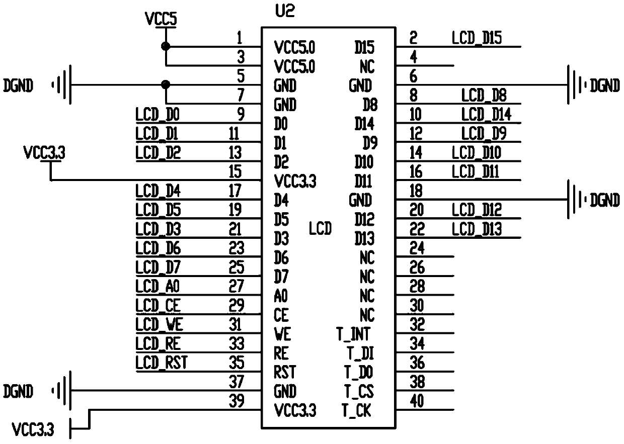
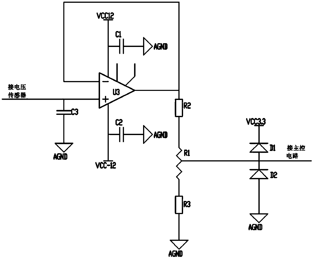
[0035] See attached figure 1 ~ attached Figure 8, a tower crane remote monitoring circuit with self-diagnosis function, which includes a plurality of sensors, a sampling circuit, a main control circuit, a display circuit, an alarm circuit, a relay drive circuit and a GPRS wireless communication module; the main control circuit includes a central processing unit and a self-diagnosis circuit; each sensor in the plurality of sensors is connected to the sampling circuit, and the sampling circuit and the display circuit are connected to the central processing unit of the main control circuit; the alarm circuit and The GPRS wireless communication modules are all connected with the self-diagnosis circuit of the self-diagnosis circuit of the main control circuit; .

[0036] Such as figure 1 , the sensor group composed of load cell, slewing sensor, amplitude sensor, height sensor, wind speed sensor, voltage sensor, current sensor and temperature sensor collects the operating para...


PUM


Abstract

The invention discloses a remote tower crane monitoring circuit with a self-diagnostic function. The remote tower crane monitoring circuit comprises a plurality of sensors, a sampling circuit, a main control circuit, a display circuit, an alarming circuit, a relay driving circuit and a GPRS (General Packet Radio Service) wireless communication module, wherein the main control circuit comprises a central processing unit and a self-diagnostic circuit; each sensor is connected with the sampling circuit; the sampling circuit and the display circuit are connected with the central processing unit of the main control circuit; the alarming circuit and the GPRS wireless communication module are connected with the self-diagnostic circuit of the main control circuit; the sensors comprise a weighing sensor, a rotary sensor, an amplitude variation sensor, a height sensor, an airspeed sensor, a voltage sensor, a current sensor and a temperature sensor. The tower crane remote monitoring circuit with the self-diagnostic function has the advantages that the remote monitoring on an operation state of a tower crane can be realized, the operation safety and reliability of the tower crane are improved, and the like.

Description

technical field [0001] The invention relates to a tower crane remote monitoring circuit with self-diagnosis function. Background technique [0002] Tower crane (tower crane) referred to as tower crane, also known as tower crane, consists of three parts: metal structure, working mechanism and electrical system. The metal structure includes the tower body, the boom and the base, etc. The working mechanism has four parts: lifting, luffing, slewing and walking. The electrical system includes motors, controllers, power distribution cabinets, connecting lines, signals and lighting devices, etc. With the extensive use of tower cranes in the construction industry in recent years, various tower crane operation safety accidents have occurred frequently due to violations of regulations and overruns of tower cranes and interference and collisions of tower crane groups, resulting in huge losses of life and property. The experience and lessons of safety accidents show that it is necess...

Claims


Application Information

Patent Timeline
Patent Type & Authority Applications(China)
IPC IPC(8): B66C23/88
Inventor 李郑郑红梅丁曙光潘友杰阚文年
Owner ANHUI CONSTR MACHINERY
Learn More