
A fixture box on a drill pipe joint

A drill pipe joint and fixture box technology, applied in the direction of manufacturing tools, workpiece clamping devices, etc., can solve the problems of low work efficiency and unstable shackle torque, and achieve the effects of high work efficiency, simple action and strong practicability

Active Publication Date: 2015-08-19
JIAOZUO JINBIAO MACHINERY MFG
View PDF7 Cites 0 Cited by
  • Summary
  • Abstract
  • Description
  • Claims
  • Application Information

AI Technical Summary

Problems solved by technology

[0004] The technical problem to be solved by the present invention is that the shackle torque is unstable and the working efficiency is low. Therefore, the present invention provides a fast, convenient and stable torque clamp box

Method used


Image

  • A fixture box on a drill pipe joint
  • A fixture box on a drill pipe joint
  • A fixture box on a drill pipe joint

Examples


Embodiment Construction

[0019] The present invention will be further described in detail below in conjunction with the accompanying drawings and specific embodiments.

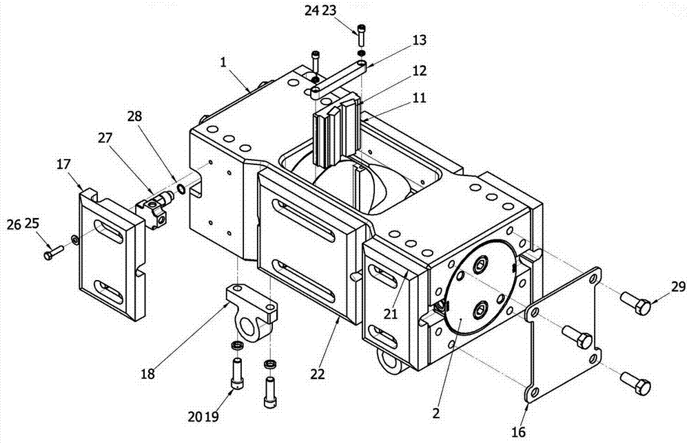
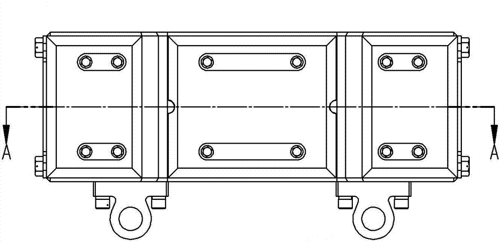
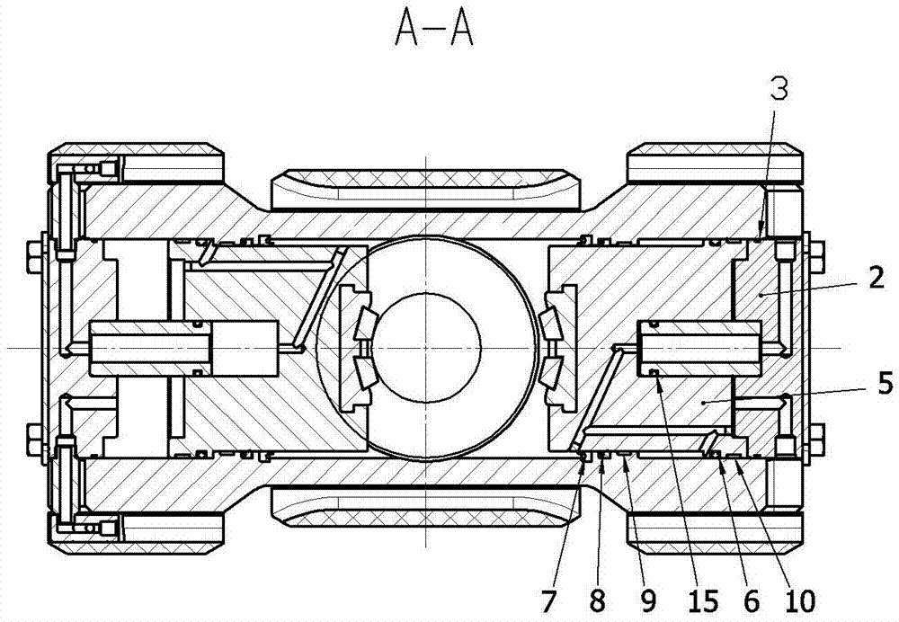
[0020] Such as figure 1 As shown, the present invention provides a clamp box on a drill pipe joint, which is characterized in that the clamp box is mainly composed of a housing 1, a positioning box 4 located at one end of the housing and a locking box located at the other end of the housing , there is a certain piston 5 in the positioning box 4, a locking piston in the locking box, pliers are installed on the ends of the fixed piston 5 and the locking piston, and buffering is installed on both sides of the housing 1. device; the pliers are composed of die fixing plate 11, pliers die insert 12 and pliers baffle bar 13, the die fixing plate 11 is fixed on the fixed piston 5 and the end of the locking piston, the The pliers die insert 12 is fixed on the die fixing plate 11, and the pliers baffle strip 13 is fixed on the end of the fixed...


PUM


Abstract

The invention discloses a fixture box on a drill pipe joint. The fixture box mainly comprises a shell, a positioning box and a locking box, wherein the positioning box is positioned at one end of the shell, and the locking box is positioned at the other end of the shell. A positioning piston is arranged in the positioning box, a locking piston is arranged in the locking box, clamps are mounted at ends of the positioning piston and the locking piston, and buffers are mounted on two sides of the shell. According to the technical scheme, the positioning piston and the locking piston are mounted in the shell of the fixture box, stable in movement trace and placed in relatively sealed clamping spaces, so that clamping torsion moment is stable, and external damage is avoided.

Description

technical field [0001] The invention relates to a fixture box used on a mud pump drill pipe joint. Background technique [0002] Before welding the drill pipe joint of the mud pump, a shackle test must be done on the joint, so that the thread and bearing surface can be loaded accordingly, so that the cooperation of the joint can be tested, thereby reducing the possibility of the thread being pierced by the mud. [0003] In the prior art, when breaking and unloading, due to the large torque inertia and the deviation of loading and unloading pressure, it is very easy to damage the joint. In addition, there are some problems that the torque requirement cannot be met, and the surface of the joint is not beautiful. , The shackle experiment takes a long time and the work efficiency is low. Contents of the invention [0004] The technical problem to be solved by the invention is that the shackle torque is unstable and the work efficiency is low. Therefore, the invention provides...

Claims


Application Information

Patent Timeline
Patent Type & Authority Patents(China)
IPC IPC(8): B25B11/00
CPCB25B11/00
Inventor 史文涛许可王和平秦峰成初石莹莹
Owner JIAOZUO JINBIAO MACHINERY MFG
Learn More