
Optical fiber laser cutting head for laser cutting system

A laser cutting and fiber laser technology, applied in laser welding equipment, welding equipment, metal processing equipment and other directions, can solve the problems of short service life of the laser head protection mirror, disorder of the internal transmission direction of the air flow, reducing the effect of auxiliary laser cutting, etc. Save workload, improve cutting quality and efficiency, stable center position

Active Publication Date: 2014-02-05
WUXI QINGYUAN LASER TECH
View PDF7 Cites 16 Cited by
  • Summary
  • Abstract
  • Description
  • Claims
  • Application Information

AI Technical Summary

Problems solved by technology

However, due to the relatively small torque of manual adjustment and the loose coordination of related parts, it is easy to appear the problem that the position of the focus center changes after the focus length is adjusted, which affects the cutting quality
[0008] 2. In the protective mirror device, the service life of the laser head protective mirror is short, and it needs to be disassembled and replaced frequently in actual use
The airflow in this blowing method is vertically injected into the internal airway of the laser head, so the airflow direction in the interior is disordered, which reduces the gas flow velocity to a certain extent, thereby reducing the effect of auxiliary laser cutting

Method used


Image

  • Optical fiber laser cutting head for laser cutting system
  • Optical fiber laser cutting head for laser cutting system
  • Optical fiber laser cutting head for laser cutting system

Examples


Embodiment Construction

[0031] The present invention will be further described below in conjunction with specific drawings and embodiments.

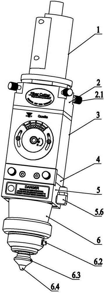
[0032] As shown in the figure: the fiber laser cutting head for the laser cutting system in the embodiment is mainly composed of an optical fiber connector 1, a horizontal adjustment device 2, a focusing device 3, a protective mirror device 4, and an air guiding device connected coaxially from top to bottom. The device 5 and the cutting head 6 are composed of several parts.

[0033] like Figure 1~4As shown in the figure, the focusing device 3 in the embodiment is mainly composed of a focus adjusting seat 3.1, a focusing knob seat 3.2, a focusing dial 3.3, a focusing knob 3.4, a focusing barrel connecting plate 3.5, a focusing bolt 3.6, a locking The screw 3.7, the first O-ring 3.8, the focusing tube 3.9, the second O-ring 3.10 and the focusing lens 3.11 are composed.

[0034] The focus adjusting seat 3.1 is provided with a focusing tube slideway 3.1a, and th...


PUM


Abstract

The invention relates to an optical fiber laser cutting head for a laser cutting system. The optical fiber laser cutting head comprises an optical fiber connector, a horizontal adjusting device, a focus adjusting device, a protective glass device, a gas guiding device and a cutting head which are connected sequentially from the top to the bottom in a coaxial mode. The optical fiber laser cutting head is characterized in that in the focus adjusting device, a focus adjusting barrel is assembled in a focus adjusting barrel slide movably, a focus adjusting knob base is fastened on a focus adjusting base, a focus adjusting dial and the focus adjusting knob base are fastened together, a focus adjusting knob is clamped in an inner hole in a focus adjusting knob base through the focus adjusting dial, and the focus adjusting knob can rotate smoothly but can not move axially. A clamping groove is formed in the outer side of a focus adjusting barrel connecting plate, an annular boss is arranged on the inner side of the focus adjusting knob, the center of the annular boss and the rotation center of the focus adjusting knob are biased, and the annular boss is embedded in the clamping groove in a matched mode. A focus lens is arranged in the focus adjusting barrel. The optical fiber laser cutting head is fast in focus adjusting and can guarantee cutting quality, protective glass is convenient to detach, and adjusting is not required after the protective glass is detached and installed. The gas guiding device can effectively assist laser cutting and improve cutting quality.

Description

technical field [0001] The invention relates to an optical fiber laser cutting head for a laser cutting system, belonging to the technical field of laser processing. Background technique [0002] Laser cutting is to scan the surface of the material with a focused laser beam of high power density, heat the material to thousands or even tens of thousands of degrees Celsius in a very short time, so that the material is instantly melted or vaporized, and then the molten or vaporized material is removed from the cutting process by high-pressure gas. Blow away in the seam, so as to achieve the purpose of cutting the material. [0003] Fiber cutting is faster and more efficient than traditional cutting, with short processing time, small heat-affected zone, small thermal deformation and processing deformation. The focused spot of the laser beam is small, allowing finer micromachining, superior conduction and focusing performance, and easy control of power and energy. Compact and l...

Claims


Application Information

Patent Timeline
IPC IPC(8): B23K26/38B23K26/04B23K26/14B23K26/70
CPCB23K26/02B23K26/142B23K26/38B23K26/702
Inventor 曾军河陈继良彭文斌
Owner WUXI QINGYUAN LASER TECH
Learn More