Monitoring system

A monitoring system and monitoring process technology, applied in the field of monitoring systems, can solve problems such as the complexity of monitoring operations

Active Publication Date: 2014-01-29
APPL TECHN ETUD REAL MECANIQUES ELECTRONIQUES SYST
View PDF7 Cites 0 Cited by
  • Summary
  • Abstract
  • Description
  • Claims
  • Application Information

AI Technical Summary

Problems solved by technology

Although this type of system provides long distance visibility when the surrounding area is flat, the presence of obstacles such as mountains or buildings near the tower complicates surveillance operations by requiring especially tall towers

Method used


Image

  • Monitoring system
  • Monitoring system
  • Monitoring system

Examples


Embodiment Construction

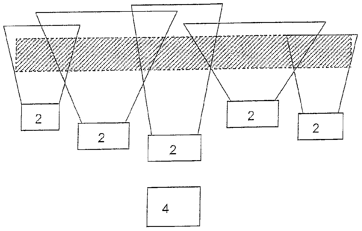
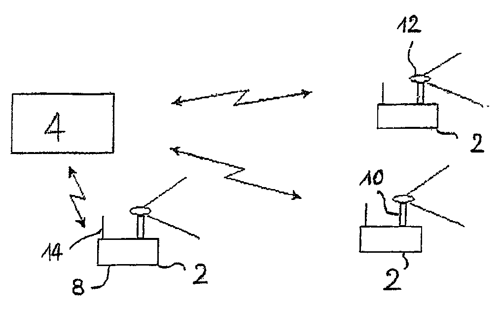
[0021] figure 1 The monitoring system represented in includes a network of monitoring stations 2 arranged to completely cover a given area and a management unit 4 located at a distance from said monitoring stations and designed to communicate with each of said monitoring stations .

[0022] In the described construction method, the management unit is able to communicate with five monitoring stations. Advantageously, the management unit accommodates four to six monitoring stations. It should be understood that the number of monitoring stations is a strategic rather than technical choice, and thus the invention is not limited to the number of management units and monitoring stations shown here. where mentioned, by figure 1 The area to be monitored, indicated by the shaded area in , covers roughly the linear distance of fifty kilometers within which the system must detect and identify intrusions and traversals. The depth of the area to be monitored is determined to enable v...


PUM


Abstract

The invention relates to a monitoring system comprising means for detecting presence in a determined zone as well as means of identifying detected intruders. The means of detection are distributed over various mobile monitoring stations (2). A network is formed by these monitoring stations and by a management centre (4) which is adapted for communicating with each of the monitoring stations and which comprises software means adapted for automatically calculating the configuration to be given to the network in order to monitor this zone and to thus optimize the means available as a function of the zone. The calculation of the configuration of the network is performed as a function of input data comprising on the one hand characteristics pre-recorded in the management centre and on the other hand elements of information which are at least in part provided from said monitoring stations once in place on said zone.

Description

technical field [0001] The present invention relates to surveillance systems designed to detect the presence of intruders in a given area. Background technique [0002] In the field of intrusion detection, unlike radar, which only produces an imperceptible alarm, the use of optoelectronics enables the user to immediately judge whether the intrusion is benign, usually by combining the data from the optical sensor with the image processing system and display and storage. The system is realized by combining the data from the image processing system. [0003] Surveillance systems can be used in various applications such as border control, industrial facilities and construction sites. Surveillance systems exist that include watchtowers on top of which cameras widely scan the area to be monitored. Although this type of system provides long distance visibility when the surrounding area is flat, the presence of obstacles such as mountains or buildings near the tower complicates su...

Claims


Application Information

Patent Timeline
Patent Type & Authority Applications(China)
IPC IPC(8): G08B13/196G01S13/86H04N7/18G08B25/10G06T17/05
CPCG01S13/867G08B13/1966G08B25/10G08B13/19645G08B13/196H04N7/181G01S13/04G01S13/886
Inventor B·阿维尼翁L·托马斯
Owner APPL TECHN ETUD REAL MECANIQUES ELECTRONIQUES SYST
Why Eureka
Try Eureka