Direct-current input end inverted connection protecting circuit, direct-current input end inverted connection protecting method and direct-current input equipment
A technology of reverse polarity protection circuit and DC input terminal, applied in the direction of emergency protection circuit devices, electrical components, etc., can solve the problems of increasing system power consumption, reducing system efficiency, and continuous loss, so as to increase power consumption, improve reliability, and cost low effect
- Summary
- Abstract
- Description
- Claims
- Application Information
AI Technical Summary
Problems solved by technology
Method used
Image
Examples
Embodiment 1
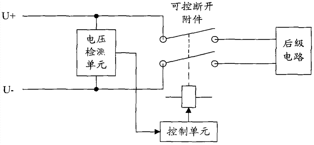
[0073] Such as figure 2 As shown, this embodiment provides a DC input terminal anti-reverse connection protection circuit, which includes: a controllable disconnection accessory, a voltage detection unit and a control unit.
[0074] The controllable disconnecting accessory is connected between the DC input terminal and the subsequent circuit.
[0075] The voltage detection unit is connected in parallel between the positive and negative poles of the DC input terminal, and is used for real-time detection of the voltage signal between the positive and negative poles of the DC input terminal, and sends the detection result to the control unit.
[0076] The control unit is respectively connected to the voltage detection unit and the controllable disconnection accessory, and is used to determine whether the positive and negative poles of the DC input terminal are reversed according to the detection result of the voltage detection unit, and if it is determined to be reversed, contro...
Embodiment 2
[0085] This embodiment provides a DC input terminal anti-reverse connection protection circuit (structural schematic diagram and figure 2 same), wherein the control unit is specifically used for:
[0086] After the anti-reverse polarity protection circuit at the DC input terminal is powered on,
[0087] If the detection result of the voltage detection unit is that the voltage between the positive and negative poles of the DC input terminal is a negative voltage, it is determined that the positive and negative poles of the DC input terminal are reversely connected, and the controllable disconnection accessory is controlled to disconnect;
[0088] If the detection result of the voltage detection unit is that the voltage between the positive and negative poles of the DC input terminal is a positive voltage, it is determined that the positive and negative poles of the DC input terminal are positively connected, and the controllable disconnection attachment is controlled to pull i...
Embodiment 3
[0112] This embodiment provides a DC input terminal anti-reverse connection protection circuit (structural schematic diagram and figure 2 same), wherein the control unit includes a first sampling circuit and a first comparison circuit, that is, the control unit does not need to use the logic control device described in Embodiments 1 to 2, and only needs to use a hardware circuit to control the controllable disconnection Attachment snaps in / off.
[0113] The first sampling circuit is used to sample the voltage signal detected by the voltage detection unit in real time to obtain a voltage sampling signal, and send the voltage sampling signal to the first comparison circuit.
[0114] A voltage reference reverse judgment signal is preset in the first comparison circuit for comparing the voltage sampling signal with the voltage reference reverse judgment signal, if the voltage sampling signal is greater than the voltage reference reverse judgment signal Judging the signal, it is ...
PUM
 Abstract
Description
Claims
Application Information
 - R&D
- Intellectual Property
- Life Sciences
- Materials
- Tech Scout
- Unparalleled Data Quality
- Higher Quality Content
- 60% Fewer Hallucinations
Browse by: Latest US Patents, China's latest patents, Technical Efficacy Thesaurus, Application Domain, Technology Topic, Popular Technical Reports.
© 2025 PatSnap. All rights reserved.Legal|Privacy policy|Modern Slavery Act Transparency Statement|Sitemap|About US| Contact US: help@patsnap.com


