
Driving device and bicycle with same

A driving device and bicycle technology, which are applied in the directions of rider driving, vehicle components, transportation and packaging, etc., can solve the problems of large differences in bicycle speed, large space occupied by bicycles, and large storage space for bicycles, so as to reduce weight and carry The effect of convenience and low manufacturing cost

Inactive Publication Date: 2014-01-29
吴晓东
View PDF6 Cites 3 Cited by
  • Summary
  • Abstract
  • Description
  • Claims
  • Application Information

AI Technical Summary

Problems solved by technology

However, because bicycles take up a lot of space, are generally heavy, and are not convenient to carry, they are not suitable for use in some occasions. For example, bicycles are not allowed to be carried into the public transportation system
Therefore, there are certain difficulties in solving the problem of the last mile from the bus station to the destination, solving the problem between bus transfers and solving the problem that bicycles are stored at home and occupy too much space.
Solve the problem of the last mile from the bus station to the destination and the problem of bus transfer. If the walking speed is relatively slow, it is much different from the bicycle speed

Method used


Image

  • Driving device and bicycle with same
  • Driving device and bicycle with same
  • Driving device and bicycle with same

Examples


Embodiment 1

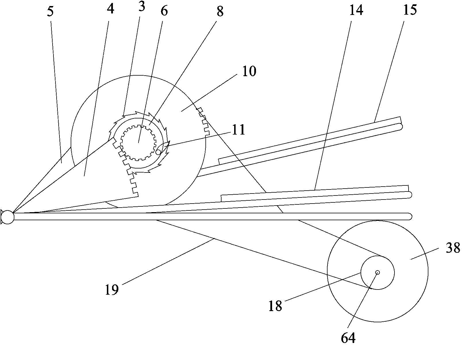
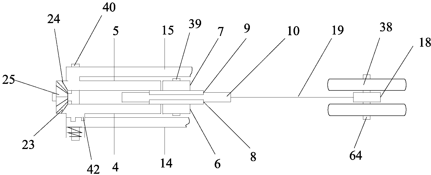
[0108] Such as figure 1 and figure 2As shown, the drive device of the present invention includes a drive gear 10, a first ratchet mechanism, a second ratchet mechanism, a first sector gear 4 (ie, the left sector gear), a second sector gear 5 (ie, the right sector gear), a first pedal 14 (i.e. left pedal), second pedal 15 (i.e. right pedal) and bevel gear set. The first ratchet mechanism and the second ratchet mechanism are symmetrically arranged on both sides of the drive gear 10 and can alternately drive a drive gear 10 to rotate in the same direction; the first sector gear 4 meshes with the first ratchet mechanism and drives the first ratchet mechanism Rotate, the second sector gear 5 meshes with the second ratchet mechanism and drives the second ratchet mechanism to rotate; one end of the first pedal 14 is the stepping end, the other end is the connecting end, the connecting end of the first pedal 14 is connected to the first sector One end of the gear 4 connected to the...

Embodiment 2

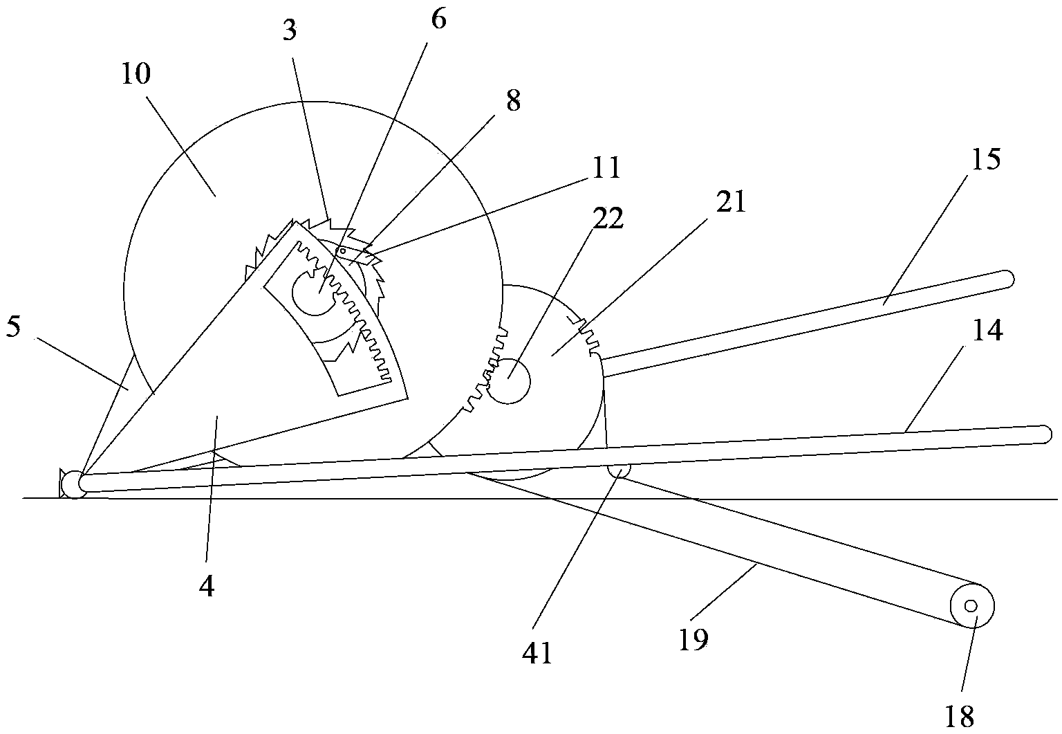
[0113] Such as image 3 and Figure 4 As shown, the difference between this embodiment and Embodiment 1 is that a coaxial and fixed speed change mechanism is added, and the speed change mechanism includes a secondary main gear 21 and a secondary pinion gear 22 to increase the output speed of the driving device . The driving gear 10 meshes with the secondary pinion 22 and drives it to rotate, and the secondary pinion 22 drives the secondary main gear 21 to rotate. Because the outer diameter of the wheel of the secondary pinion 22 is much smaller than that of the driving gear 10, when the driving gear 10 rotates once, it will drive the secondary pinion 22 to rotate several times, and simultaneously the secondary main gear 21 will also rotate with the secondary The same number of turns of the pinion, thus increasing the speed of rotation.

[0114] In order to ensure that the drive gear 10 rotates clockwise, the first sector gear 4 and the second sector gear 5 adopt image 3 T...

Embodiment 3

[0117] Such as Figure 5 to Figure 8 As shown, the structure of the driving device of the third embodiment is basically the same as that of the first embodiment, the difference is that the driving gear 10 is placed horizontally, and the first ratchet mechanism and the second ratchet mechanism are located on the lower and upper sides of the driving gear 10 respectively. A sector gear 4 and a second sector gear 5 are located on the lower and upper sides of the driving gear 10 respectively, while the first pedal 14 and the second pedal 15 are located above the driving gear 10 . Simultaneously the structure of described bevel gear set in embodiment three is also different from embodiment one, in this embodiment, described bevel gear set comprises the 4th bevel gear 26, the 5th bevel gear 27, the 6th bevel gear 28 and the seventh bevel gear 29, the fourth bevel gear 26 is connected with one end of the first pedal 14 through an engagement device, the fifth bevel gear 27 is fixedly c...


PUM


Abstract

The invention discloses a driving device and a bicycle with the same. The driving device comprises a driving gear, a first ratchet wheel mechanism, a second ratchet wheel mechanism, a first sector gear, a second sector gear, a first pedal, a second pedal and bevel gear sets. The driving gears are used for outputting driving force. The first ratchet wheel mechanism and the second ratchet wheel mechanism are symmetrically arranged on the two side faces of the driving gear and are used for driving the driving gear to rotate in the same direction. The first sector gear and the second sector gear are meshed with the first ratchet wheel mechanism and the second ratchet wheel mechanism respectively to drive the first ratchet wheel mechanism and the second ratchet wheel mechanism to rotate. The first pedal and the second pedal are used for driving the first sector gear and the second sector gear to rotate respectively. The bevel gear sets are arranged at the end, connected with a second shaft, of the first sector gear and the end, connected with the second shaft, of the second sector gear respectively and are used for enabling the first pedal and the second pedal to make reciprocal movement. The bicycle with the driving device is small and portable, convenient to store after being folded, equal to a common bicycle in riding speed, high in practicability and convenient to popularize and apply.

Description

technical field [0001] The invention relates to a driving device and a bicycle, in particular to a driving device driven by pedaling and a bicycle with the driving device, belonging to the field of transportation devices. Background technique [0002] Present bicycle is widely used as a kind of personal transportation. The utility model has the advantages of energy saving, environmental protection, convenient use and physical exercise. However, because bicycles take up a lot of space, are generally heavy, and are not convenient to carry, they are not suitable for use in some occasions. For example, bicycles are not allowed to be carried into the public transport system. Therefore, there are certain difficulties for solving the problem of the last mile of the bus station to the destination, solving the problem between bus transfers and solving the problem that bicycles are stored at home and take up too much space. To solve the problem of the last mile from the bus station ...

Claims


Application Information

Patent Timeline
Patent Type & Authority Applications(China)
IPC IPC(8): B62M1/24
Inventor 吴晓东吴雨瞳
Owner 吴晓东
Learn More