a coating machine
A coating machine and knife coating technology, applied in the direction of coating, the device for coating liquid on the surface, etc., can solve the problems of easy bending of the tool holder, affecting the advancing pace, insufficient rigidity of the tool holder, etc., to improve the adjustment accuracy, The effect of eliminating internal gaps and high product quality
- Summary
- Abstract
- Description
- Claims
- Application Information
AI Technical Summary
Problems solved by technology
Method used
Image

Examples
Embodiment 1
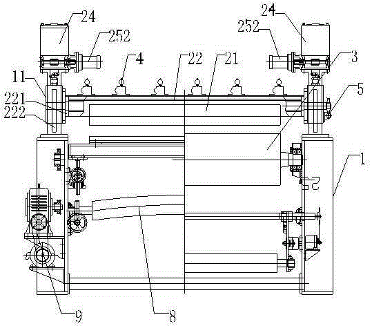
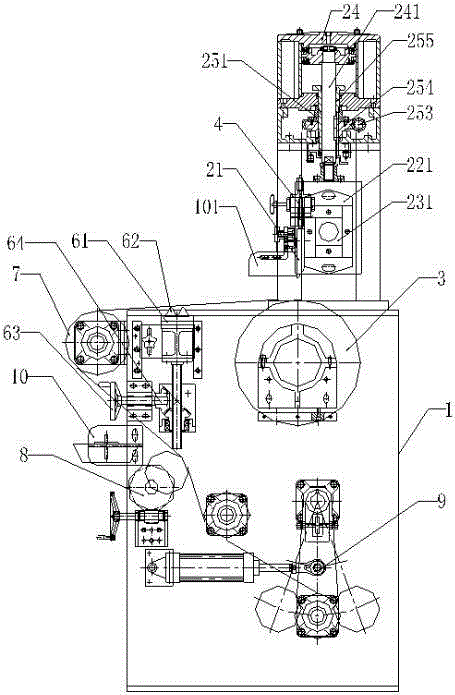
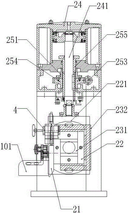
[0029] Such as Figure 1-3 As shown, it includes a frame 1, a coating knife mechanism arranged on the frame 1, and a roller 3. The coating knife mechanism includes a coating knife 21, a knife rest 22 for installing the coating knife 21, a reinforcement device connecting the knife rest 22, and a connecting knife The lifting device of the frame 22 and the gap adjusting device for eliminating the internal gap of the lifting device, the gap adjusting device includes a gap eliminating part 251, and the roller 3 is provided with a reinforcement, the reinforcement is an inner support plate or an inner cylinder, and the inner support The plate and the inner cylinder are arranged inside the roller, and then threads or fins are added in the gap between the supporting plate or the inner cylinder and the roller to further improve its overall strength.
[0030] The reinforcing device includes a first reinforcing part 231 and a second reinforcing part 232. The first reinforcing part 231 is ...
Embodiment 2
[0035] The processing technology of the above-mentioned roller 3 is as follows: 1. Forming: bore the inner hole on the blank first, and then turn the outer circle to make the quality of the outer circle meet the requirements; 2. Reinforcement: add a support plate or The inner cylinder, and weld the reinforcement and the roller as a whole; 3. Stress relief: carry out stress relief treatment on the processed roller until it reaches the processing standard; 4. Subsequent treatment: finish turning and finishing Grinding, dynamic balancing and heat treatment are repeated until the final machining accuracy is achieved. The roller processed by the above processing method has good rigidity, high dynamic balance precision, is not easy to deform after long-term use, and rotates smoothly without jumping, which provides the basis for the precision of the coating. The radial runout of the roller has been increased from ≤0.012mm to ≤0.008mm; thus meeting the product requirements of the coat...
Embodiment 3
[0037] The rest are the same as the above-mentioned embodiment, the difference is that, as figure 2 As shown, the coating machine also includes an idler roller 7 for the carrier, a bending roller 8 for spreading, and a tension adjustment device 9 for adjusting the tension of the entire fabric, which is set in the opposite direction of coating by the coating knife 21 There is a material blocking mechanism 101 for blocking material (the material blocking mechanism is an existing technology, which will not be described in detail here), and a material receiving box for receiving the remaining paint on the roller is also arranged under the idler roller to avoid excess paint dripping into the equipment Or on the ground, pollute the environment, but also can be reused, saving and environmental protection.
[0038] Through the above-mentioned technical solution, the beneficial effect of the technical solution of the present invention is: the setting of the reinforcing device, the rei...
PUM
 Abstract
Description
Claims
Application Information
 - R&D
- Intellectual Property
- Life Sciences
- Materials
- Tech Scout
- Unparalleled Data Quality
- Higher Quality Content
- 60% Fewer Hallucinations
Browse by: Latest US Patents, China's latest patents, Technical Efficacy Thesaurus, Application Domain, Technology Topic, Popular Technical Reports.
© 2025 PatSnap. All rights reserved.Legal|Privacy policy|Modern Slavery Act Transparency Statement|Sitemap|About US| Contact US: help@patsnap.com