Rotating device having single ball bearing

A ball bearing, rotating device technology, applied in parts of pumping devices for elastic fluids, machines/engines, liquid fuel engines, etc., can solve problems such as power wastage, not well solved, and voids, etc. To solve the effect of vibration

Inactive Publication Date: 2010-09-29
NS MICRO MOTOR TECH CORP
View PDF5 Cites 1 Cited by
  • Summary
  • Abstract
  • Description
  • Claims
  • Application Information

AI Technical Summary

Problems solved by technology

[0006] However, such a design only focuses on the preload function of the inner ring 181. For the outer ring 182, only the top surface is supported by the top edge of the shaft tube 12, and the bottom surface lacks any supporting structure. This makes the outer ring 182 actually very easy to drive the integral ball bearing 18 down with its own weight because there is no support below. Although the spring 20 can still push the integral ball bearing 18 upwards to the normal position immediately by releasing the preload, this is also It shows that the integral ball bearing 18 is not in a stable position, resulting in the aforesaid preloading function not being fully exerted, and the ball bearing 18 is still prone to form a gap with the top edge of the shaft tube 12, thereby causing the ball bearing 18 to vibrate , noise, power consumption and other issues have not been well resolved

Method used


Image

  • Rotating device having single ball bearing
  • Rotating device having single ball bearing
  • Rotating device having single ball bearing

Examples


Embodiment Construction

[0026] The present invention will be described in detail below in conjunction with the accompanying drawings and embodiments. Before the present invention is described in detail, it is noted that in the following description, similar elements are denoted by the same numerals.

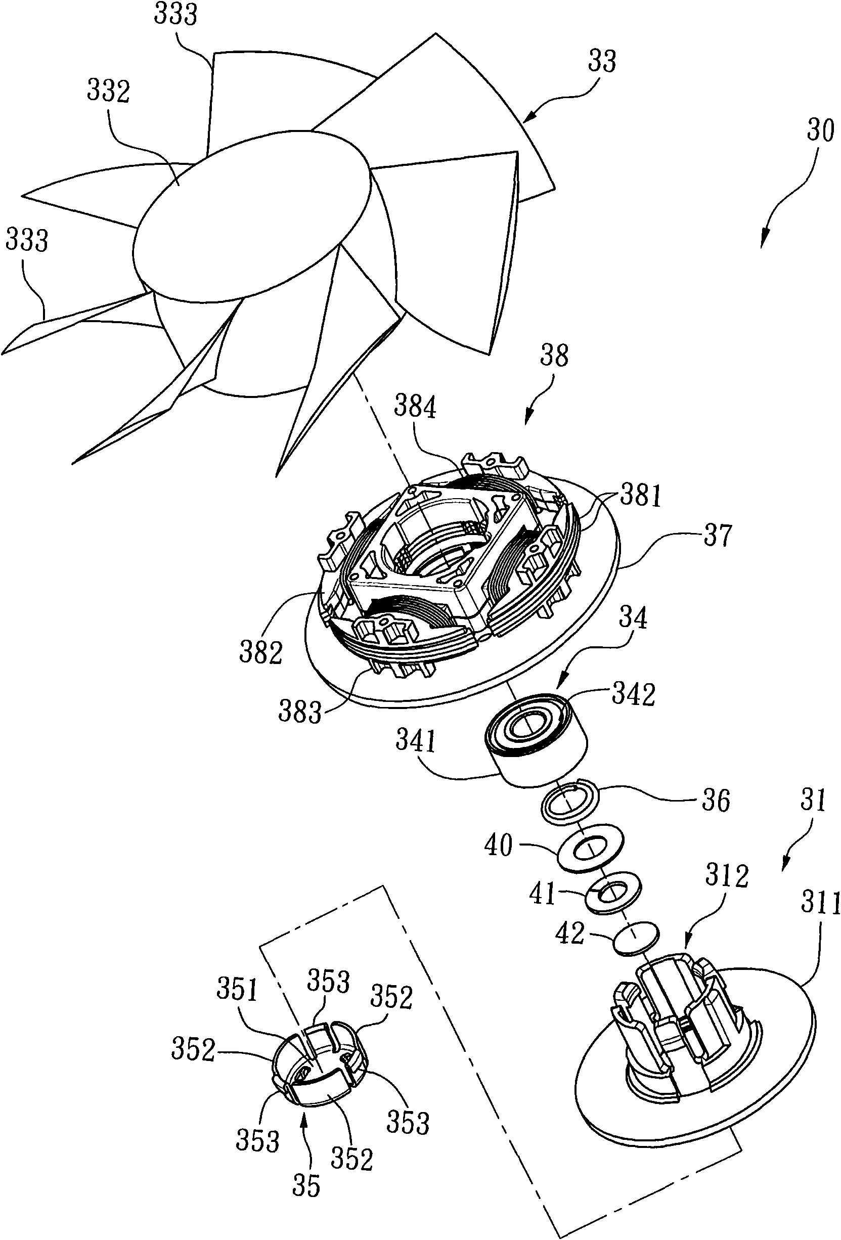
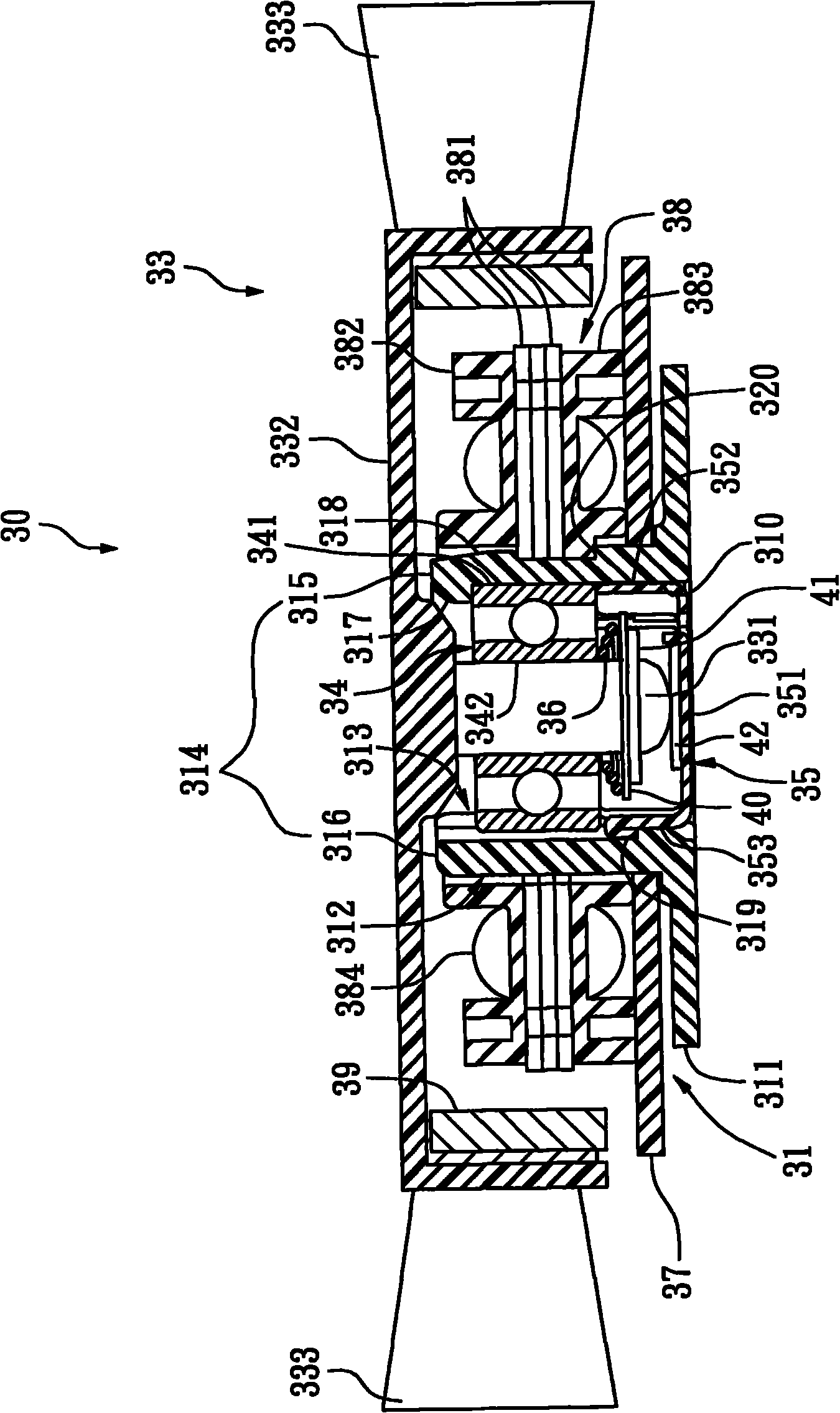
[0027] refer to figure 2 , image 3 , the first preferred embodiment of the rotating device 30 with a single ball bearing of the present invention comprises a base 31, a rotor unit 33 pivotally arranged on the base 31, a ball used to support the smooth rotation of the rotor unit 33 Bearing 34, a sleeve 35 that is engaged with the base 31 and is used to abut against the ball bearing 34, and an elastic member 36 that is used to prestress the ball bearing 34, the base 31 has a limit A ring wall 311 with a perforation 310, and a shaft tube 312 integrally extended from the ring wall 311, the perforation 310 is only seen in the image 3 .

[0028] And because this rotating device 30 is mainly applied in ...


PUM


Abstract

The invention relates to a rotating device having a single ball bearing, which comprises a base, a rotor unit pivoted on the base, a ball bearing for supporting the rotor unit to rotate smoothly, a sleeve engaged with the base for resisting against the ball bearing and an elastic element for exerting a pre-stress on the ball bearing. Aiming at the axle tube of the base and the sleeve, a specific structure is designed for the invention to hold and limit the base and top of an external ring of the ball bearing through a positioning part of the sleeve and the axle tube and support the bottom of an inner ring of the ball bearing by exerting the pre-press through the elastic element, therefore keeping the ball bearing at a stable position and solving the problems such as vibration, noise, power waste, and the like.

Description

technical field [0001] The invention relates to a rotating device, in particular to a rotating device for a fan or a motor. Background technique [0002] The ball bearing of a general motor is composed of an outer ring, an inner ring, and a plurality of balls located between the inner ring and the outer ring. When the ball bearing is in operation, the aforementioned balls are between the inner ring and the outer ring. Rotation, but the ball bearings are prone to internal clearance, which will affect the operation and performance of the motor, such as vibration, noise, power consumption and other shortcomings. Therefore, it is necessary to apply appropriate preload on the ball bearings. Solve and improve the above-mentioned problems caused by internal gaps. [0003] see figure 1 , is a kind of fan motor 10 disclosed in the eighteenth figure of the invention patent case No. I258538 of Taiwan, China. A circuit board 13 located on the shaft tube 12, a stator 14 electrically c...

Claims


Application Information

Patent Timeline
Patent Type & Authority Applications(China)
IPC IPC(8): F04D29/00F04D29/059
Inventor 洪银农
Owner NS MICRO MOTOR TECH CORP
Why Eureka
Try Eureka