A new energy vehicle battery management system
A battery management system, a technology for new energy vehicles, applied in electric vehicles, battery circuit devices, current collectors, etc., can solve problems such as electric shock accidents, poor safety, and power system power outages
- Summary
- Abstract
- Description
- Claims
- Application Information
AI Technical Summary
Problems solved by technology
Method used
Image
Examples
Embodiment 1
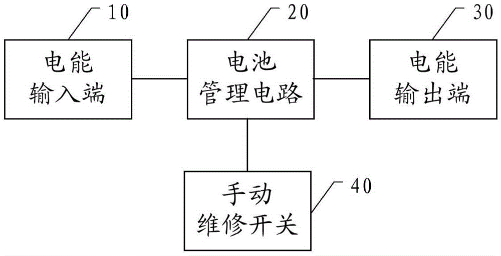
[0029] figure 1 It is a structural diagram of a battery management system for a new energy vehicle disclosed in the embodiment of this application.
[0030] Such as figure 1 As shown, the battery management system disclosed in this embodiment includes a power input terminal 10, a battery management circuit 20, a power output terminal 30 and a manual maintenance switch 40, wherein the battery management circuit 20 is connected to the power input terminal 10, the power output terminal 30, and the manual maintenance switch respectively. The service switch 40 is connected.
[0031] The power input terminal 10 is used to receive power from the battery and output power to the battery management circuit 20;
[0032] The battery management circuit 20 is the power heart of the new energy vehicle. It is used to receive and distribute electric energy from the electric energy input terminal 10. In addition to supplying power to the power system, it also supplies power to the instrument ...
Embodiment 2
[0037] figure 2 It is a structural diagram of a battery management system of a new energy vehicle disclosed in another embodiment of the present application.
[0038] Such as figure 2 As shown, the battery management system disclosed in this embodiment includes a power input terminal 10, a battery management circuit 20, a power output terminal 30, and a disconnect switch 41, wherein the battery management circuit 20 is connected to the power input terminal 10 and the power output terminal 30 through wires respectively. connect.
[0039] The power input terminal 10 is used to receive electric energy from the battery, including the input terminal positive pole 11 and the input terminal negative pole 12, which are respectively connected to the battery management circuit 20 through wires, the input terminal positive pole 11 is used to connect with the positive pole of the battery, and the input terminal negative pole 12 Used to connect to the negative terminal of the battery. ...
Embodiment 3
[0045] image 3 It is a structural diagram of a battery management system of a new energy vehicle disclosed in another embodiment of the present application.
[0046] Such as image 3 As shown, the battery management system disclosed in this embodiment includes a power input terminal 10, a battery management circuit 20, a power output terminal 30, and a disconnect switch 41, wherein the battery management circuit 20 is connected to the power input terminal 10 and the power output terminal 30 through wires respectively. connect.
[0047] The power input terminal 10 is used to receive electric energy from the battery, including the input terminal positive pole 11 and the input terminal negative pole 12, which are respectively connected to the battery management circuit 20 through wires, the input terminal positive pole 11 is used to connect with the positive pole of the battery, and the input terminal negative pole 12 Used to connect to the negative terminal of the battery.
...
PUM
 Abstract
Description
Claims
Application Information
 - R&D Engineer
- R&D Manager
- IP Professional
- Industry Leading Data Capabilities
- Powerful AI technology
- Patent DNA Extraction
Browse by: Latest US Patents, China's latest patents, Technical Efficacy Thesaurus, Application Domain, Technology Topic, Popular Technical Reports.
© 2024 PatSnap. All rights reserved.Legal|Privacy policy|Modern Slavery Act Transparency Statement|Sitemap|About US| Contact US: help@patsnap.com


