
Self-propelled movable formwork for construction of double-rectangle water conservancy aqueduct

A mobile formwork and self-propelled technology, which is applied in the erection/assembly of bridges, bridges, buildings, etc., can solve the problems of large construction loss, a lot of labor and material consumption, and high foundation bearing capacity requirements. Simple structure and good linear effect

Active Publication Date: 2014-01-22
ZHENGZHOU NEW DAFANG HEAVY IND & TECH
View PDF4 Cites 6 Cited by
  • Summary
  • Abstract
  • Description
  • Claims
  • Application Information

AI Technical Summary

Problems solved by technology

[0003]Although the existing and commonly used full house bracket method is mature and widely used, its shortcomings are unavoidable:
[0004]1. The initial cost investment is relatively large. If the progress similar to the construction of the present invention is achieved, at least two half-span and half-full hall supports and two sets of formwork need to be invested;
[0005]2. The construction period is long, and each hole requires preloading inspection, which wastes a lot of time;
[0006]3. The full house support method has high requirements on the bearing capacity of the foundation, and is not suitable for high groove piers. It is difficult to construct when crossing ditches, rivers and other landforms;
[0007]4. The treatment of the weak foundation and the re-cultivation after construction also need to consume a lot of labor and materials;
[0008]5. The construction loss of the full hall support is relatively large

Method used


Image

  • Self-propelled movable formwork for construction of double-rectangle water conservancy aqueduct
  • Self-propelled movable formwork for construction of double-rectangle water conservancy aqueduct
  • Self-propelled movable formwork for construction of double-rectangle water conservancy aqueduct

Examples


Embodiment Construction

[0068] The present invention will be further described below in conjunction with embodiment (accompanying drawing):

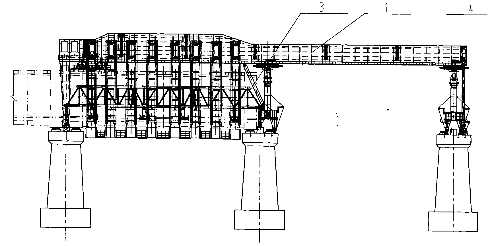
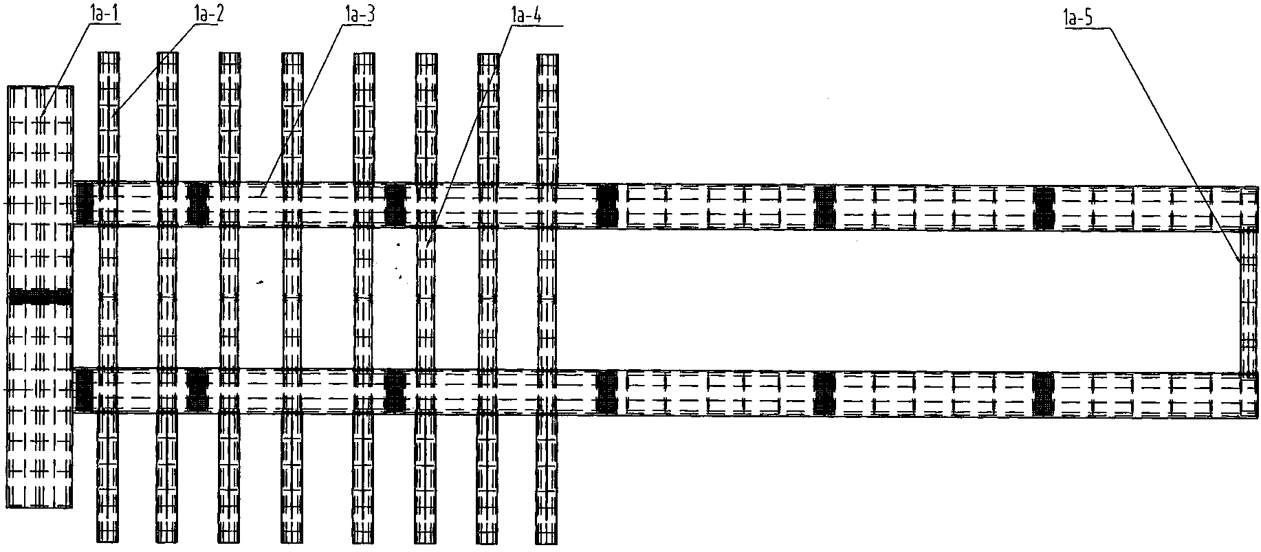
[0069] like figure 1 , 2 , 3, 4, 5, 6, 7, and 8, the self-propelled mobile formwork for the construction of double rectangular hydraulic aqueducts of the present invention includes an outer beam system (1), an outer mold system (2), an inner beam system ( 3), the outer mold system (4), the electric control system (5) and the hydraulic system (6); the outer beam system (1) is the main bearing system of the equipment, mainly composed of the outer beam (1a) , outer beam No. 1 leg (1b), outer beam No. 2 leg (1c), outer beam No. 3 leg (1d), outer beam No. 4 leg (1e), and outer beam rear travel (1f). where the outer beam (1a) (see Figure 9~14 As shown) is in the form of a box-shaped composite beam, which is in the form of double longitudinal beams (1a-3). The distance between the centers of the double longitudinal beams (1a-3) is 9.5 meters. -5), the rear connec...


PUM


Abstract

Provided is a self-propelled movable formwork for construction of a double-rectangle water conservancy aqueduct. The self-propelled movable formwork for construction of the double-rectangle water conservancy aqueduct comprises an outer beam system (1), an outer mould system (2), inner beam systems (3), inner mould systems (4), an electronic control system (5), a hydraulic system (6) and the like. The outer beam system (1) is a main load bearing system of the self-propelled movable formwork, and mainly comprises an outer beam (1a), a first outer beam leg (1b), a second outer beam leg (1c), a third outer beam leg (1d), a fourth outer beam leg (1e) and a rear outer beam walking portion (1f), wherein a box-shaped composite beam mode is adopted by the outer beam (1a), the outer beam (1a) is of a double-beam form, the center distance between the double beams is 9.5m, and the double beams are combined into a whole through two end-connecting beams, eight middle-connecting beams and sixteen outriggers which are symmetrical in a left-and-right mode. An outer girder serves as a main bearing structure of an aqueduct construction machine, the load of the pouring state is transmitted to the top of a poured pier through the third outer beam leg and the fourth outer beam leg, and the poured pier straddles the front portion and the rear portion.

Description

technical field [0001] The invention relates to a self-propelled mobile formwork used for the in-situ cast-in-place construction of a rectangular water conservancy aqueduct, in particular to the construction of a rectangular double-groove aqueduct. Background technique [0002] With the deepening of the construction of the middle line of my country's South-to-North Water Diversion, more and more artificial above-ground river sections have appeared. Usually, above-ground rivers use aqueducts as water channels. These large-tonnage hydraulic aqueducts are all made of reinforced concrete. Aqueduct loads. [0003] Although the existing commonly used full house bracket method is mature and widely used, its shortcomings are unavoidable: [0004] 1. The initial cost investment is relatively large. If the construction progress similar to that of the present invention is achieved, at least two half-span and half-full hall supports and two sets of formwork need to be invested; [0005...

Claims


Application Information

Patent Timeline
IPC IPC(8): E01D21/06
Inventor 高自茂陈德利代宇周治国赵芳星张艳丽韩权立贾力锋张红军高建华
Owner ZHENGZHOU NEW DAFANG HEAVY IND & TECH
Learn More