Full-automatic rotary u-turn machine

A rotary U-turn machine, fully automatic technology, applied in the direction of conveyor objects, transportation and packaging, etc., can solve the problem that rectangular tiles cannot be rotated and turned, sprayed or printed, etc., to achieve simple structure, stable process, and increase the stress area Effect

Inactive Publication Date: 2015-07-22
NANAN XINJIE MACHINERY
View PDF7 Cites 0 Cited by
  • Summary
  • Abstract
  • Description
  • Claims
  • Application Information

AI Technical Summary

Problems solved by technology

[0004] The invention provides a fully automatic rotary turning machine, the main purpose of which is to overcome the defect that the rectangular tiles on the existing ceramic tile production line cannot be rotated and turned to adapt to spraying or printing

Method used


Image

  • Full-automatic rotary u-turn machine
  • Full-automatic rotary u-turn machine
  • Full-automatic rotary u-turn machine

Examples


Embodiment Construction

[0023] Specific embodiments of the present invention will be described below with reference to the accompanying drawings.

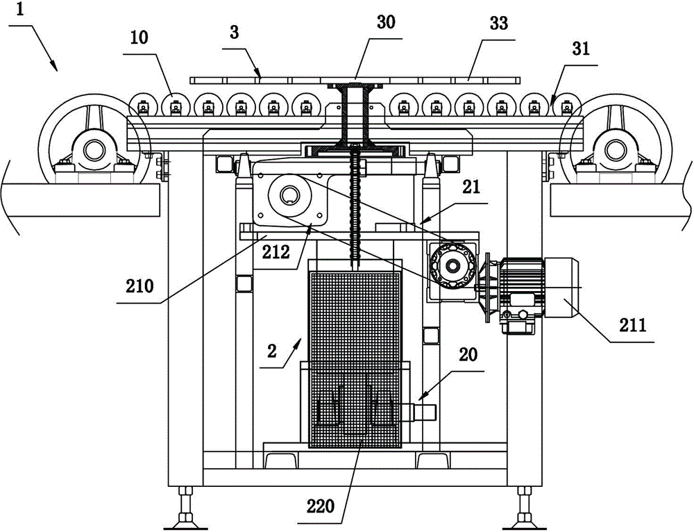
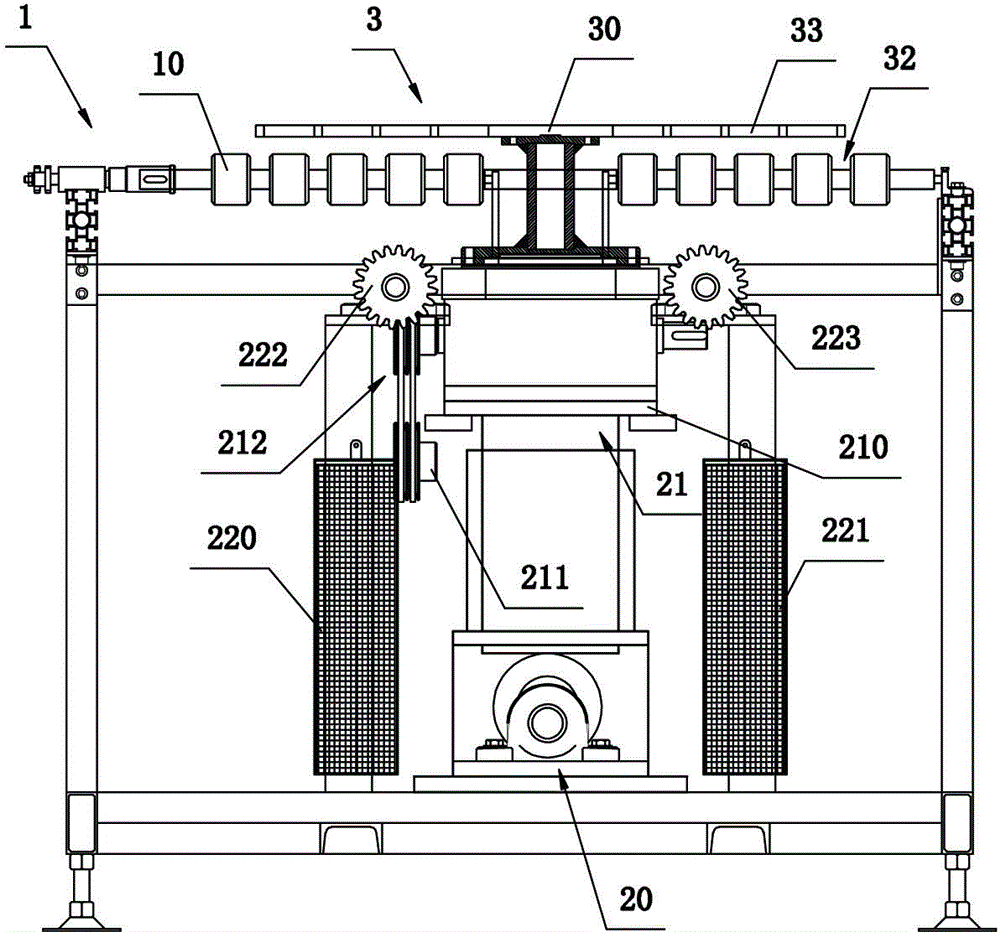
[0024] refer to figure 1 and figure 2 . A fully automatic rotary U-turn machine, comprising a stick transmission mechanism 1, a rotating lifting mechanism 2 located below the stick transmission mechanism 1 and a lifting frame 3, the stick sleeve on the stick transmission mechanism 1 is provided with a stick tube, and the stick The barrel is provided with a plurality of segment-shaped stick barrels 10, and each segment-shaped stick barrel 10 is arranged at intervals along the length direction of the stick. The holding frame 3 is a grid-like holding frame formed by the vertical crossing of a plurality of horizontal frame plates and longitudinal frame plates. Compatible with grid 33. The grids 33 on the lifting frame 3 have the same size, and the areas occupied by the segmented sticks 10 are consistent, the transverse frame plates are located in the gap...


PUM


Abstract

The invention relates to a full-automatic rotary u-turn machine which comprises a rod transmission mechanism, a rotary lifting mechanism located below the rod transmission mechanism and a lifting frame. Rod barrels are sleeved on rods on the rod transmission mechanism, a frame plate of the lifting frame is located in a gap between every two adjacent rod barrels, the height of the lifting frame is smaller than radius difference between each rod barrel and each rod, a support part is arranged on the lifting frame, an output end of the rotary lifting mechanism is connected to the lower surface of the support part, and the rotary lifting mechanism comprises a lifting device used for jacking up the lifting frame and a rotating device used for rotating the jacked-up lifting frame. The full-automatic rotary u-turn machine is simple in structure and high in automation, and rotary u-turn operation of tiles is realized by the aid of automatic control of the rotary limiting mechanism on the lifting frame; since the whole process is completed through matching of equipment, the full-automatic rotary u-turn machine has the advantages of efficiency, convenience and rapidness; in addition, the size of the lifting frame can fit with those of the tiles, therefore the whole rotary u-turn process is stable.

Description

technical field [0001] The invention relates to a U-turn equipment on a ceramic tile production line, in particular to a fully automatic rotary U-turn machine. Background technique [0002] Ceramic tiles need to be sprayed or printed on their surface during the production process. In the current production line, the sprayed or printed area is often fixed, but due to different tile specifications, especially in some rectangular tiles, the long side Sometimes the two ends of the ceramic tile are not in the spraying or printing area. At this time, it is necessary to rotate the tile so that its two ends are in the spraying or printing area, and then complete the spraying or printing operation. In addition, there are other processes in the production and processing of tiles that need to be rotated and turned around. There is an urgent need for equipment that can realize fully automatic turning and turning in the production of tiles. [0003] There is no device for rotating and t...

Claims


Application Information

Patent Timeline
Patent Type & Authority Patents(China)
IPC IPC(8): B65G47/244
Inventor 林桂生
Owner NANAN XINJIE MACHINERY
Why Eureka
Try Eureka