Automatic cutting device for rod body

A technology of automatic cutting device and rod body, applied in metal processing and other directions, can solve the problems of low cutting efficiency and poor cutting accuracy, and achieve the effect of improving cutting efficiency and cutting accuracy

Active Publication Date: 2015-06-24
HUAIBEI YUXIN NEW MATERIAL
View PDF7 Cites 0 Cited by
  • Summary
  • Abstract
  • Description
  • Claims
  • Application Information

AI Technical Summary

Problems solved by technology

[0004] The production process of fiber-reinforced plastic anchors and fiber-reinforced plastic bars is similar. Their last processing step is cutting. The traditional cutting method is manual operation. When the fiber-reinforced plastic anchor reaches the required length, the staff uses Cutting with a cutting saw, this cutting method has the problems of low cutting efficiency and poor cutting accuracy

Method used


Image

  • Automatic cutting device for rod body
  • Automatic cutting device for rod body
  • Automatic cutting device for rod body

Examples


Embodiment 2

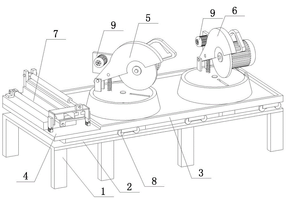
[0026] Embodiment 2 of the present invention, such as figure 1 As shown, an automatic cutting device for a rod body includes a frame body 1, a walking track 2, a cutting saw installation groove 3, a rod body positioning and stacking device support plate 4, a cutting saw A5, a cutting saw B6 and a rod body positioning and stacking device 7, The walking track 2 is arranged on the top of the frame body 1, the cutting saw installation groove 3 is fixedly connected with the rod body positioning stacking device supporting plate 4, the bottom of the cutting saw installation groove 3 is provided with a walking wheel 8, and the walking wheel 8 is arranged on the walking track 2; Both the cutting saw A5 and the cutting saw B6 are located in the cutting saw installation groove 3, and both the cutting saw A5 and the cutting saw B6 are provided with a traction device 9;

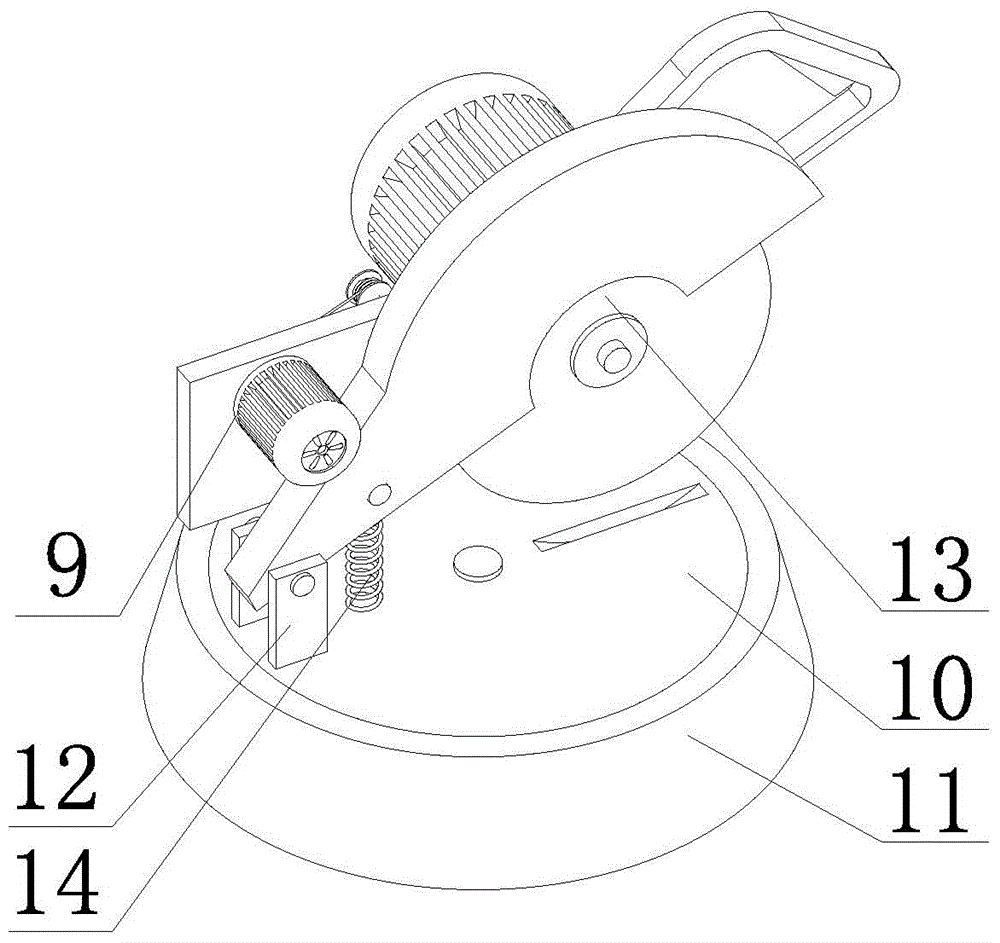
[0027] Such as figure 2 As shown, the structures of the cutting saw A5 and the cutting saw B6 are exactly the same, w...


PUM


Abstract

The invention discloses an automatic cutting device for a rod body. The automatic cutting device comprises a frame body (1), waling rails (2), a cutting saw mounting groove (3), a rod body locating and stacking device supporting plate (4), a cutting saw A (5), a cutting saw B (6) and a rod body locating and stacking device (7). The walking rails (2) are arranged at the top of the frame body (1), the cutting saw mounting groove (3) is fixedly connected with the rod body locating and stacking device supporting plate (4), walking wheels (8) are arranged at the bottom of the cutting saw mounting groove (3), and the walking wheels (8) are arranged on the walking rails (2). The cutting saw A (5) and the cutting saw B (6) are both arranged in the cutting saw mounting groove (3), and traction devices (9) are arranged on the cutting saw A (5) and the cutting saw B (6) respectively. The rod body locating and stacking device (7) is arranged on the rod body locating and stacking device supporting plate (4). The automatic cutting device can carry out automatic cutting, automatically completes stacking, does not need manual operations, and has the advantages of being high in cutting efficiency and high in cutting precision.

Description

technical field [0001] The invention relates to a cutting device, in particular to an automatic cutting device for an anchor rod body and a reinforcement rod body. Background technique [0002] Fiber-reinforced plastic bolts have the advantages of high specific strength, good safety, corrosion resistance, strong designability, and convenient construction, and are mostly used for coal mine roadway support. With the development of science and technology, bolts are not only used in mines, but also in engineering technology, which can actively reinforce slopes, tunnels and dams. It is used more and more widely. [0003] In the prior art, steel bars used to build high-rise buildings are gradually replaced by fiber-reinforced plastic bars. Because fiber-reinforced plastic bars have the same physical properties as steel bars and have the advantage of not rusting, they are widely used in the construction field. application. [0004] The production process of fiber-reinfor...

Claims


Application Information

Patent Timeline
Patent Type & Authority Patents(China)
IPC IPC(8): B26D11/00B26D3/02B26D7/01B26D7/32B26D7/26
Inventor 崔志军应伟明耿琛松
Owner HUAIBEI YUXIN NEW MATERIAL
Why Eureka
Try Eureka