Automatic dust removal method and device for protective net of strong ventilation device

A technology of strong ventilation and automatic dust removal, applied in the direction of cleaning methods, cleaning methods and utensils, chemical instruments and methods using gas flow, etc., can solve problems such as affecting ventilation and heat dissipation efficiency, affecting work efficiency and equipment operation, increasing power consumption, etc. , to reduce the workload of manual maintenance and cleaning, improve the efficiency of ventilation and heat dissipation, and achieve the effect of service life

Active Publication Date: 2016-06-01
STATE GRID CORP OF CHINA +1
View PDF4 Cites 0 Cited by
  • Summary
  • Abstract
  • Description
  • Claims
  • Application Information

AI Technical Summary

Problems solved by technology

[0002] In many large industrial plants, in order to ensure good ventilation and meet the environmental requirements of employees' work or the operation of various equipment, a certain number of strong ventilation devices are usually installed in the plant. To connect the indoor and outdoor air, in order to improve the ventilation efficiency, it is necessary to install a fan motor in the air duct for strong ventilation. There are two installation methods for the blowing direction of the fan motor: blowing to the indoor and outdoor, and the two installation methods coexist in the factory building that requires a large amount of ventilation. It is necessary to ensure a clean environment in the factory building. In order to prevent foreign objects such as small animals and sundries in the atmospheric environment from entering the room, affecting the work of employees or endangering the safe operation of equipment, protective nets with many gaps must be installed on both sides of the air duct. The size depends on the actual demand; and in the actual operation of the ventilation device, the sundries, dust, dirt, etc. in the air are adsorbed to the air inlet side of the protective net due to the wind force of the fan motor, and even large attachments, such as plastic Films, newspaper pieces and other foreign objects will cause partial blockage, seriously affecting its ventilation and heat dissipation efficiency, and regular cleaning is required to meet the needs of the plant; if the protective net is blocked seriously, not only the ventilation in the plant will be insufficient, but the indoor temperature will rise abnormally , affecting work efficiency and equipment operation, it may also cause high load, overload or even high temperature operation of the fan motor, and a large number of open ventilation devices will increase power consumption and affect its service life

Method used


Image

  • Automatic dust removal method and device for protective net of strong ventilation device
  • Automatic dust removal method and device for protective net of strong ventilation device

Examples


Embodiment 1

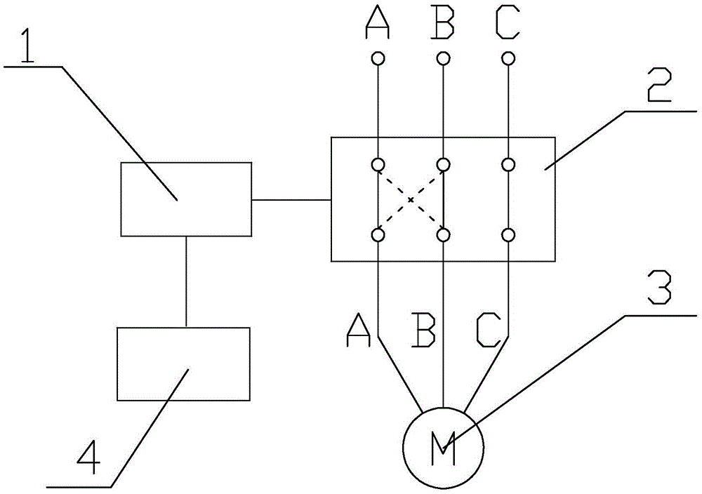
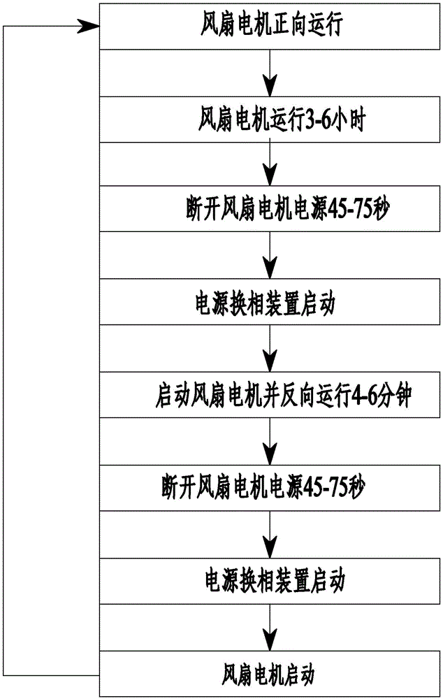
[0024] Such as figure 1 As shown, the automatic dust removal method for the protective net of the forced ventilation device described in this embodiment is that a power commutation device is connected in series in the power circuit of the fan motor 3 of the forced ventilation device, and the power supply of the fan motor 3 is changed by the power commutation device 2. The phase sequence of the fan motor 3 can be reversed, and then the direction of its blowing can be changed, and the dirt, dust and sundries adsorbed on the protective net will be blown away; the signal output terminal of the programmable logic controller 1 and the power commutation device 2 connected, connect the signal input terminal of the programmable logic controller 1 to the man-machine interface 4, and pre-set the time interval and forward and reverse operation of the power supply of the fan motor 3 through the man-machine interface 4 and the programmable logic controller 1 The running time can not only en...

Embodiment 2

[0032] In this embodiment, on the basis of Embodiment 1, the power commutator is replaced by two parallel AC contactors, so as to realize the switching of the forward and reverse rotation of the fan motor 3 . The other structures of this embodiment are exactly the same as those of Embodiment 1.

Embodiment 3

[0034] The automatic dedusting device of embodiment 1 described in the present embodiment includes a strong ventilation device for industrial workshops, the strong ventilation device is provided with a fan motor 3 and a protective net, and the fan motor 3 three-phase power supply input terminal is connected with the power supply commutation device 2 three-phase The output terminals are connected, the three-phase input terminal of the power commutation device 2 is connected to the power supply, the signal output terminal of the programmable logic controller 1 is connected to the signal input terminal of the power commutation device 2, and the signal input terminal of the programmable logic controller 1 is connected to the signal input terminal of the power commutation device 2. The man-machine interface 4 is connected.

[0035] Among them, the man-machine interface 4 adopts a touch screen, which can directly set the time interval of the power commutation operation of the fan mot...


PUM


Abstract

The invention discloses a method and device for automatically removing dust of a protective screen of a forced draft device. A power source phase-changing device is in series connection with a power source circuit of a fan motor of the forced draft device in each industrial factory so that the phase sequence of the power source of the fan motor can be changed and the fan motor can rotate reversely for a short time, and therefore the air blowing direction of the fan motor is changed and collected dirt, dust and sundries adsorbed to the protective screen of the forced draft device can be blown out. According to the method and device, the environment condition of use of the forced draft device is comprehensively considered, on the premise that normal operation of the forced draft device is guaranteed, the collected dirt, the dust, the sundries and the like on the protective screen of the forced draft device are automatically cleaned, regular manual cleaning is not needed, the maintenance workload is reduced, the draft efficiency of the device is kept, the temperature, the humidity, the cleanness of air and the like in each industrial factory can satisfy the requirements for environmental work conditions of work of workers or operation of various devices, overload running of the fan motor of the device is prevented, electric energy loss is reduced, and the service life of the device is prolonged.

Description

technical field [0001] The invention belongs to the technical field of forced ventilation devices, and in particular relates to an automatic dust removal method and device for a protective net of a forced ventilation device. Background technique [0002] In many large industrial plants, in order to ensure good ventilation and meet the environmental requirements of employees' work or the operation of various equipment, a certain number of strong ventilation devices are usually installed in the plant. To connect the indoor and outdoor air, in order to improve the ventilation efficiency, it is necessary to install a fan motor in the air duct for strong ventilation. There are two installation methods for the blowing direction of the fan motor: blowing to the indoor and outdoor, and the two installation methods coexist in the factory building that requires a large amount of ventilation. It is necessary to ensure a clean environment in the factory building. In order to prevent for...

Claims


Application Information

Patent Timeline
Patent Type & Authority Patents(China)
IPC IPC(8): B08B5/02B08B13/00
CPCB08B5/02
Inventor 咸日常
Owner STATE GRID CORP OF CHINA
Why Eureka
Try Eureka