
High frequency coil apparatus

A high-frequency coil, high-frequency structure technology, applied in measuring devices, adjusting magnetic variables, sensors, etc., can solve problems such as reducing the free space inside the tube

Active Publication Date: 2014-01-15
SIEMENS HEALTHCARE GMBH
View PDF5 Cites 0 Cited by
  • Summary
  • Abstract
  • Description
  • Claims
  • Application Information

AI Technical Summary

Problems solved by technology

However, this additional sound insulation also reduces the free space inside the tube

Method used


Image

  • High frequency coil apparatus
  • High frequency coil apparatus
  • High frequency coil apparatus

Examples


Embodiment Construction

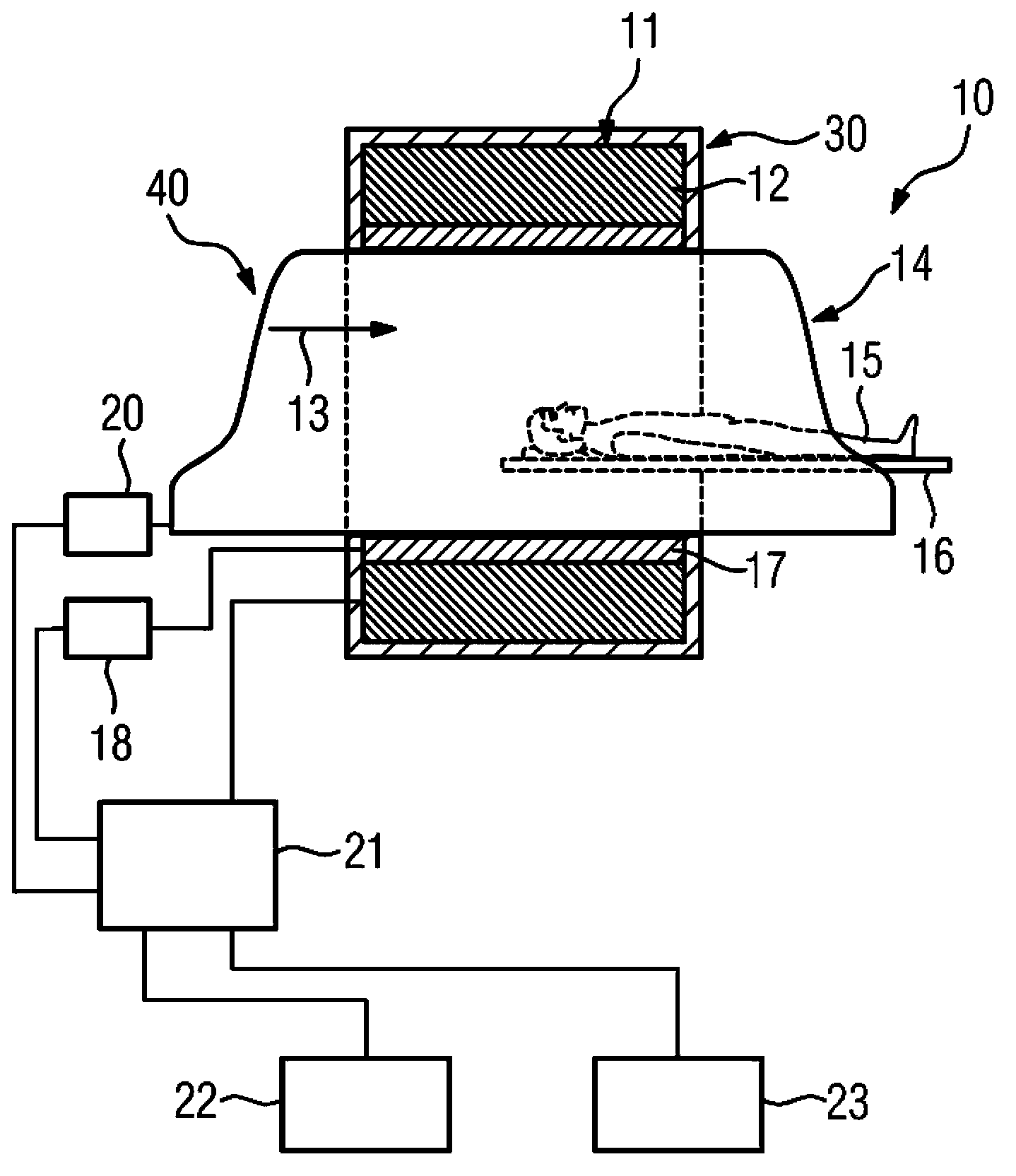
[0028] figure 1 A schematic diagram of a magnetic resonance apparatus 10 according to the invention is shown. The magnetic resonance device 10 includes a magnet unit 11 with a main magnet 12 for generating a strong and in particular constant main magnetic field 13 . In addition, the magnetic resonance apparatus 10 has a cylindrical receiving region 14 for receiving a patient 15 , wherein the receiving region 14 is surrounded in the peripheral direction by the magnet unit 11 . The patient 15 can be pushed into the receiving area 14 by means of a patient couch 16 of the magnetic resonance apparatus 10 . The patient couch 16 is here displaceably arranged inside the magnetic resonance system 10 . In addition, the magnetic resonance device 10 has a housing unit 30 surrounding the magnet unit 11 .

[0029] Furthermore, magnet unit 11 has gradient coils 17 for generating magnetic field gradients, which are used for position encoding during imaging. The gradient coils 17 are contr...


PUM


Abstract

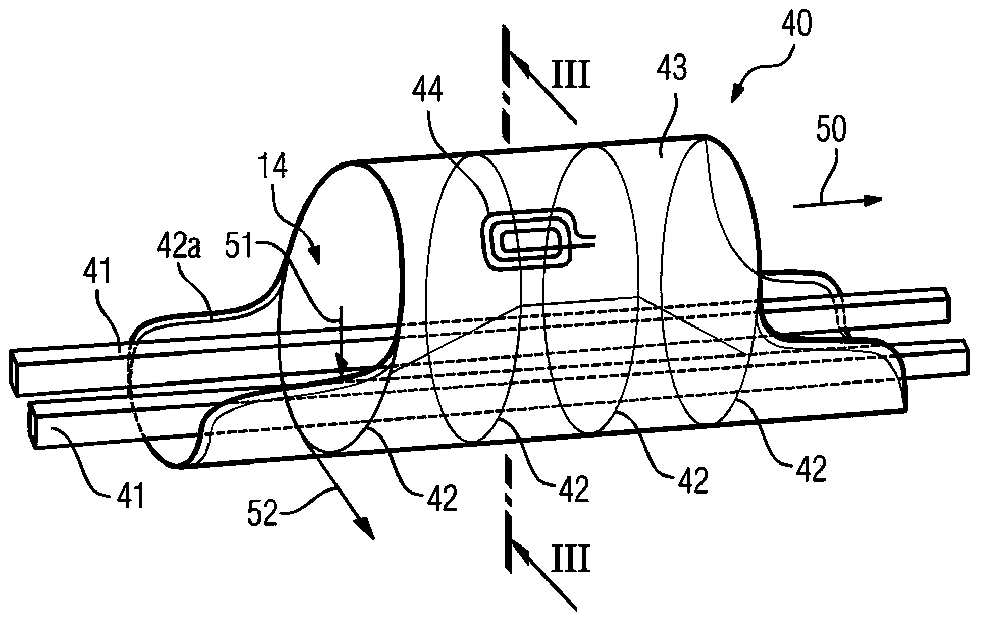
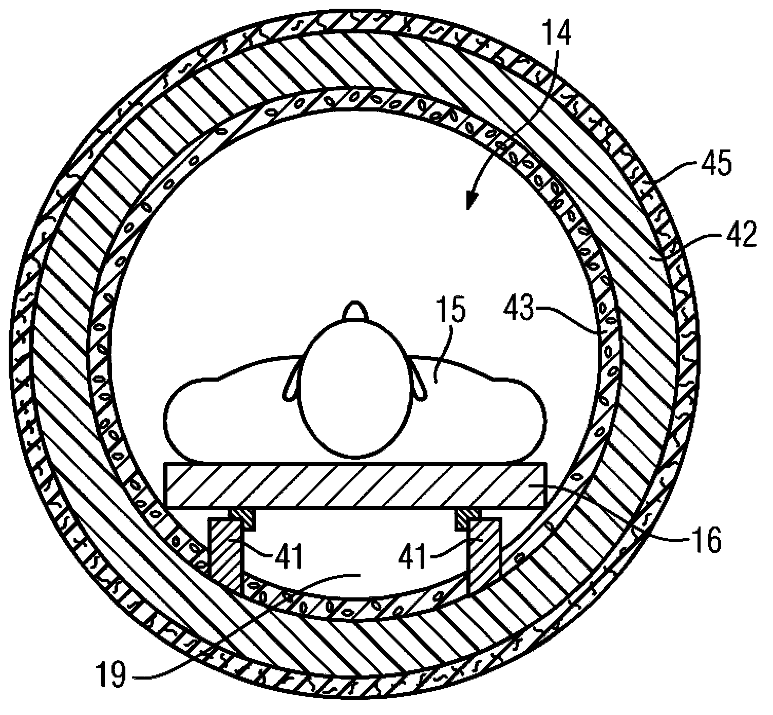
A high frequency coil apparatus for a magnetic resonance apparatus and a magnetic resonance apparatus with a high frequency coil apparatus are provided. The high frequency coil apparatus includes a receiving area for receiving a patient and structural elements. Flexible surface elements extend between the rib elements and enclose the receiving area. A high frequency structure is arranged on a structural element.

Description

technical field [0001] The invention relates to a high-frequency coil arrangement for a magnetic resonance system, which has a receiving region for receiving a patient, and to a magnetic resonance system with a high-frequency coil arrangement according to the invention. Background technique [0002] During operation, magnetic resonance systems have high operating noises, which can have an uncomfortable effect on patients who remain in the receiving area of ​​the magnetic resonance system for examinations. In particular, large vibration amplitudes occur on the area of ​​the high-frequency coil arrangement surrounding the patient receiving area, which has the consequence of high noise radiation to the patient. In addition, acoustic resonances may occur in the accommodation area, which may represent an additional noise load. Typical magnetic resonance devices have rigid and fixedly mounted housing shell units, which have high noise emissions. [0003] From the publication DE ...

Claims


Application Information

Patent Timeline
Patent Type & Authority Applications(China)
IPC IPC(8): G01R33/341G01R33/28G01R33/385
CPCA61B5/055G01R33/288G01R33/34046G01R33/34053G01R33/34061G01R33/343G01R33/381
Inventor P.迪茨M.施拉姆
Owner SIEMENS HEALTHCARE GMBH
Learn More