
Coal and rock mass stress orientation monitoring method and device

A monitoring device, coal and rock mass technology, applied in the direction of measuring force components, hydraulic/pneumatic force measurement, etc., can solve problems such as poor adaptability and timeliness, complex stress testing, and high requirements, so as to achieve small production impact and reduce testing Effects of workload, installation and operational safety

Active Publication Date: 2014-01-15
CHINA UNIV OF MINING & TECH
View PDF6 Cites 37 Cited by
  • Summary
  • Abstract
  • Description
  • Claims
  • Application Information

AI Technical Summary

Problems solved by technology

[0006] Technical problem: the purpose of the present invention is to provide a directional, multi-directional, adaptable to various stress testing problems such as complex, demanding, difficult to operate, and poor adaptability and timeliness of mining stress monitoring. Coal-loaded rock mass (original coal rock mass and broken coal rock mass), easy-to-operate coal-rock mass stress directional monitoring method and device

Method used


Image

  • Coal and rock mass stress orientation monitoring method and device
  • Coal and rock mass stress orientation monitoring method and device
  • Coal and rock mass stress orientation monitoring method and device

Examples


Embodiment 1

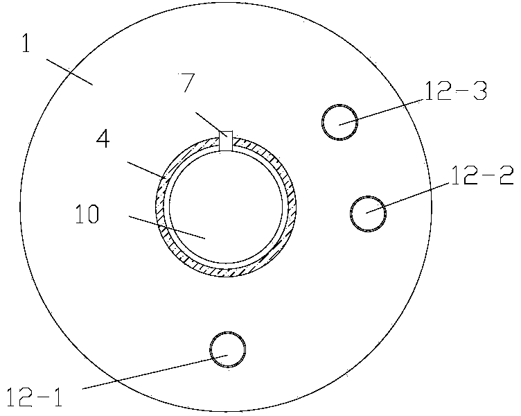
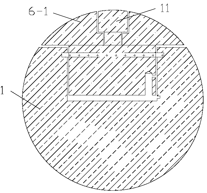
[0027] Embodiment 1, as figure 1As shown, the coal and rock mass stress directional monitoring device of the present invention is mainly composed of a three-way cylinder pressure sensor 1, a high-pressure oil pipe 2 and a three-way valve 3. The high-pressure oil pump 9 and the installation guide rod 4 are used as supporting tools. The sensor 1 is installed in the coal rock mass by installing the guide rod 4, and the cylinder body pressure sensor 1 is provided with three piston induction plates, and the three piston induction plates are respectively connected through the fixing nut 11 to each independently installed in the cylinder body pressure sensor. The piston cylinder in 1, the three piston induction sheets include the first piston induction sheet 6-1, the second Piston induction piece 6-2 and the third piston induction piece 6-3; The junction of cylinder body pressure sensor 1 and installation guide rod 4 is provided with installation rod joint 10, and installation rod jo...

Embodiment 2

[0037] Embodiment 2, according to the actual monitoring needs, if only one direction needs to be monitored, only one piston sensing plate and the piston cylinder connected to it can be set on the cylinder body pressure sensor 1, such as image 3 shown. Others are the same as in Embodiment 1, omitted.

Embodiment 3

[0038] Embodiment 3, according to the actual monitoring needs, if only two directions need to be monitored, only two piston sensing plates and the piston cylinders respectively connected to it can be arranged on the cylinder body pressure sensor 1, such as Figure 4 shown. Others are the same as in Embodiment 1, omitted.


PUM


Abstract

Provided are a coal and rock mass stress orientation monitoring method and device. The device comprises a three-way valve, a pressure gage, a high-pressure oil pump, a cylinder body pressure sensor. The cylinder body pressure sensor is provided with three piston sensing pieces which are connected with piston cylinders of the piston sensing pieces respectively. The outer ends of high-pressure oil pipes connected with the piston cylinders are connected with the pressure gage or a data converter connected with a data collector and the high-pressure oil pump through the three-way valve respectively. After the cylinder body pressure sensor is arranged in a drilling hole, the cylinder body pressure sensor bears pressure by injecting oil liquid, the piston sensing pieces can be automatically adaptive to good coupling with a coal and rock mass, and stress magnitude and changing in the three directions in the coal and rock mass can be monitored. Monitoring can be carried out on an original rock mass and in a broken coal and rock mass, the coal and rock mass stress orientation monitoring method and device can be widely used in geostress measurement, surrounding rock stability analysis and the like of mines, construction, water conservancy, roads, tunnels and underground engineering.

Description

technical field [0001] The invention relates to the technical field of coal and rock mass stress monitoring, in particular to a coal and rock mass stress directional monitoring method and device suitable for mines, and can also be used for ground stress testing and surrounding rock stability in civil engineering, water conservancy, roads, tunnels and underground projects gender analysis. Background technique [0002] The natural stress that exists in the formation without engineering disturbance is called the original rock stress, also known as the initial stress or in-situ stress. It mainly includes the self-gravity stress caused by the self-weight of the overlying strata and the structural stress caused by the geological structure. Self-weight stress σ ν =γZ, where γ is the specific gravity of the overlying coal strata, and Z is the vertical depth. Tectonic stress can be divided into modern tectonic stress and geological structural residual stress. In-situ stress is th...

Claims


Application Information

Patent Timeline
IPC IPC(8): G01L5/16G01L1/02
Inventor 王恩元王嗣衡沈荣喜刘晓斐宋大钊潘东伟
Owner CHINA UNIV OF MINING & TECH
Learn More