
Ceiling transport vehicle and article transport facility

A technology for transporting vehicles and roofs, which is applied in the direction of conveyor objects, conveyors, load blocks, etc., and can solve problems such as large spaces

Active Publication Date: 2014-01-15
DAIFUKU CO LTD
View PDF5 Cites 3 Cited by
  • Summary
  • Abstract
  • Description
  • Claims
  • Application Information

AI Technical Summary

Problems solved by technology

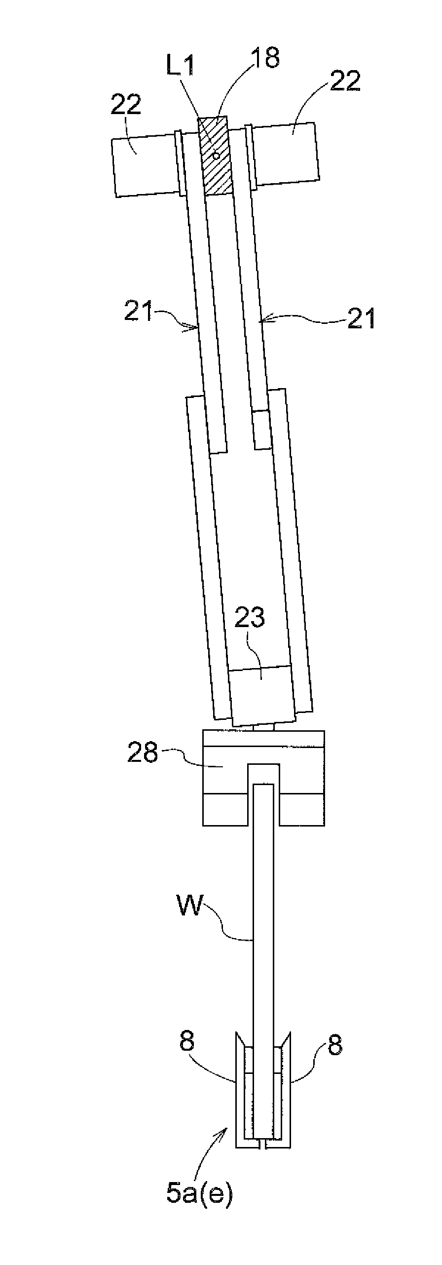
[0004] However, in the above-mentioned roof transport vehicle of Patent Document 1, since the upper connection part moves in the horizontal direction with respect to the traveling part, it is necessary to secure a space for the upper connection part to slide and move in the horizontal direction, and a large space is required for the installation of the traveling body.

Method used


Image

  • Ceiling transport vehicle and article transport facility
  • Ceiling transport vehicle and article transport facility
  • Ceiling transport vehicle and article transport facility

Examples


Embodiment Construction

[0069] Embodiments of the present invention will be described below based on the drawings.

[0070] Such as figure 1 As shown, the ceiling conveying vehicle 1 equipped in the article conveying facility is configured to be guided and supported by the traveling rail 2 provided on the ceiling, and is configured to travel along the traveling path 3 passing above the conveying target position E to convey the formed object as an article. It is a plate-shaped substrate W. In addition, in this embodiment, as the board|substrate W, the photomask used for processing of the glass substrates, such as a liquid crystal panel, is conveyed by the top conveyance vehicle 1. As shown in FIG.

[0071] In addition, the horizontal direction along the traveling direction will be referred to as the front-rear direction, and the horizontal direction perpendicular to the front-rear direction will be referred to as the lateral width direction. exist figure 1 In , the front-rear direction is indicated...


PUM


Abstract

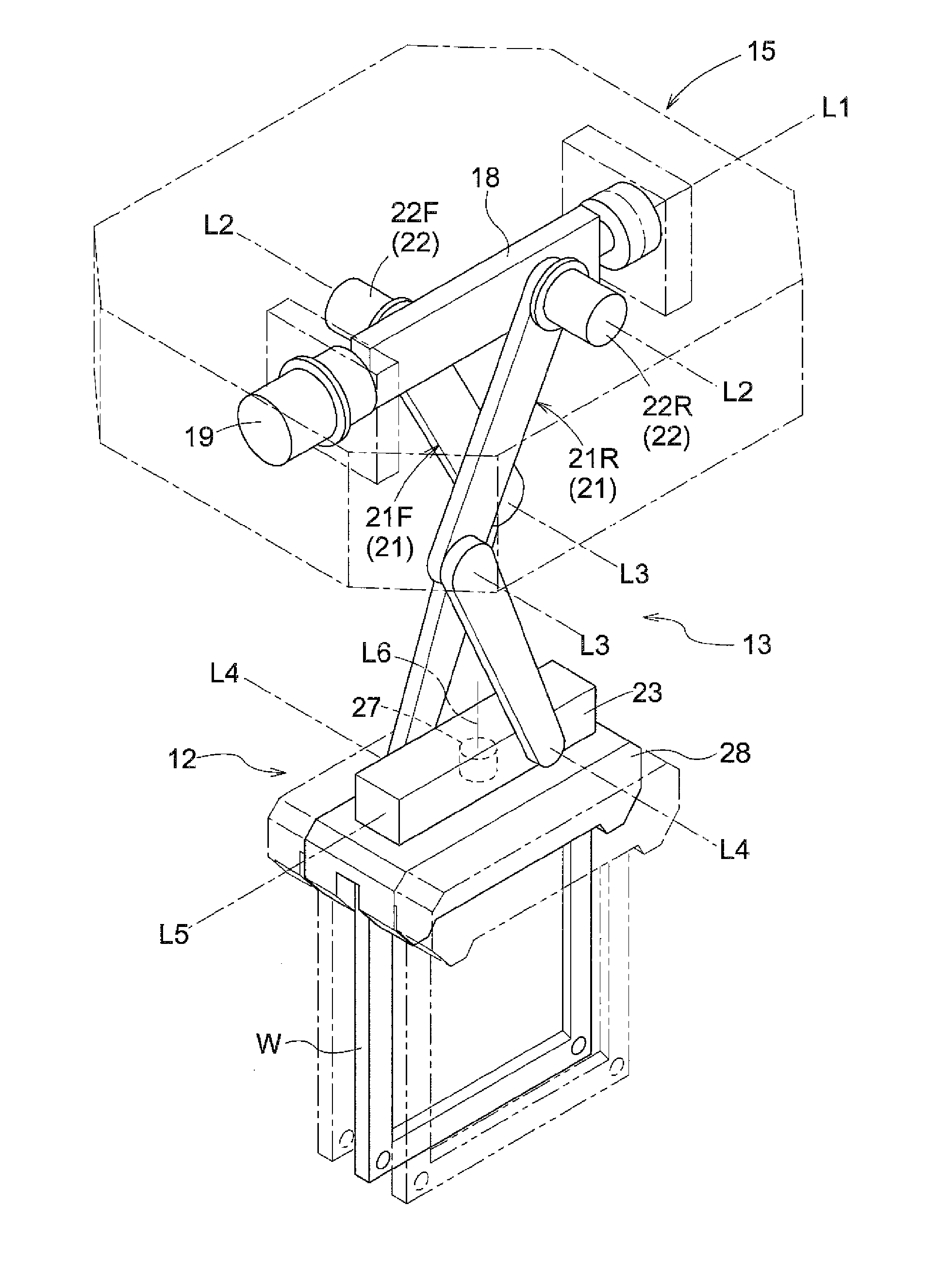
A ceiling transport vehicle has an elevation operation mechanism which elevates and operates a support body with respect to a mobile object. The elevation operation mechanism has a connecting rod mechanism which extends and retracts freely vertically, and a retraction drive unit that enables the connecting rod mechanism to extend and retract. An upper side connection unit connected with an upper end of the connecting rod mechanism is supported with respect to the mobile body to swing freely around a horizontal axis in the horizontal direction. A swing drive unit which enables the upper side connection unit to swing around the horizontal axis with respect to the body is also provided.

Description

technical field [0001] The present invention relates to a roof transport vehicle including a traveling body that travels along a travel path while being guided and supported by a travel rail disposed on the top plate side, and article transport equipment having the same. The supporting body that is suspended and supported on the traveling body and supports the article, the lifting operation mechanism that moves the supporting body up and down with respect to the traveling body, and the lifting operation mechanism is equipped with the upper end connected to the upper connection part of the traveling body and the lower end is connected to the supporting body. A link mechanism that can be freely extended and contracted in the vertical direction by being connected to the lower side connecting part of the lower side, and a telescopic drive part that is equipped with the elevating operation mechanism and makes the link mechanism expand and contract. Background technique [0002] T...

Claims


Application Information

Patent Timeline
IPC IPC(8): B66F7/06B66C11/00H01L21/677
CPCB65G47/901B65G49/061B65G2201/022
Inventor 村山繁人
Owner DAIFUKU CO LTD
Learn More