
Nail dismounting device

A technology of nail extractor and impact rod, which is applied in the field of plate removal tools, can solve the problems of laborious turning and straightening, damage to screw teeth, and difficulty in accurate knocking, etc., to achieve labor-saving turning, stable nailing operation, and easy removal Effect

Inactive Publication Date: 2014-01-15
施俊兆
View PDF8 Cites 0 Cited by
  • Summary
  • Abstract
  • Description
  • Claims
  • Application Information

AI Technical Summary

Problems solved by technology

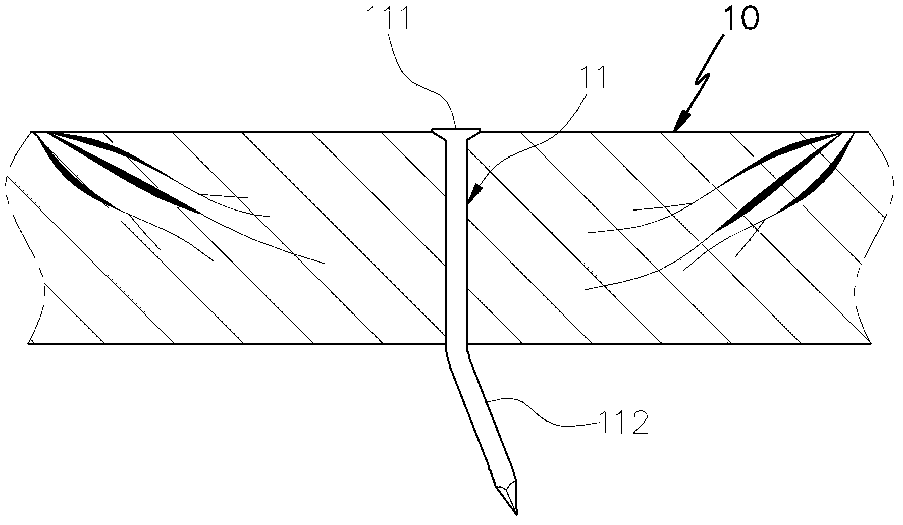
[0003] 1. In the force application operation of the pliers tool, it is necessary to turn and straighten the bent nail-in end 112 with great effort
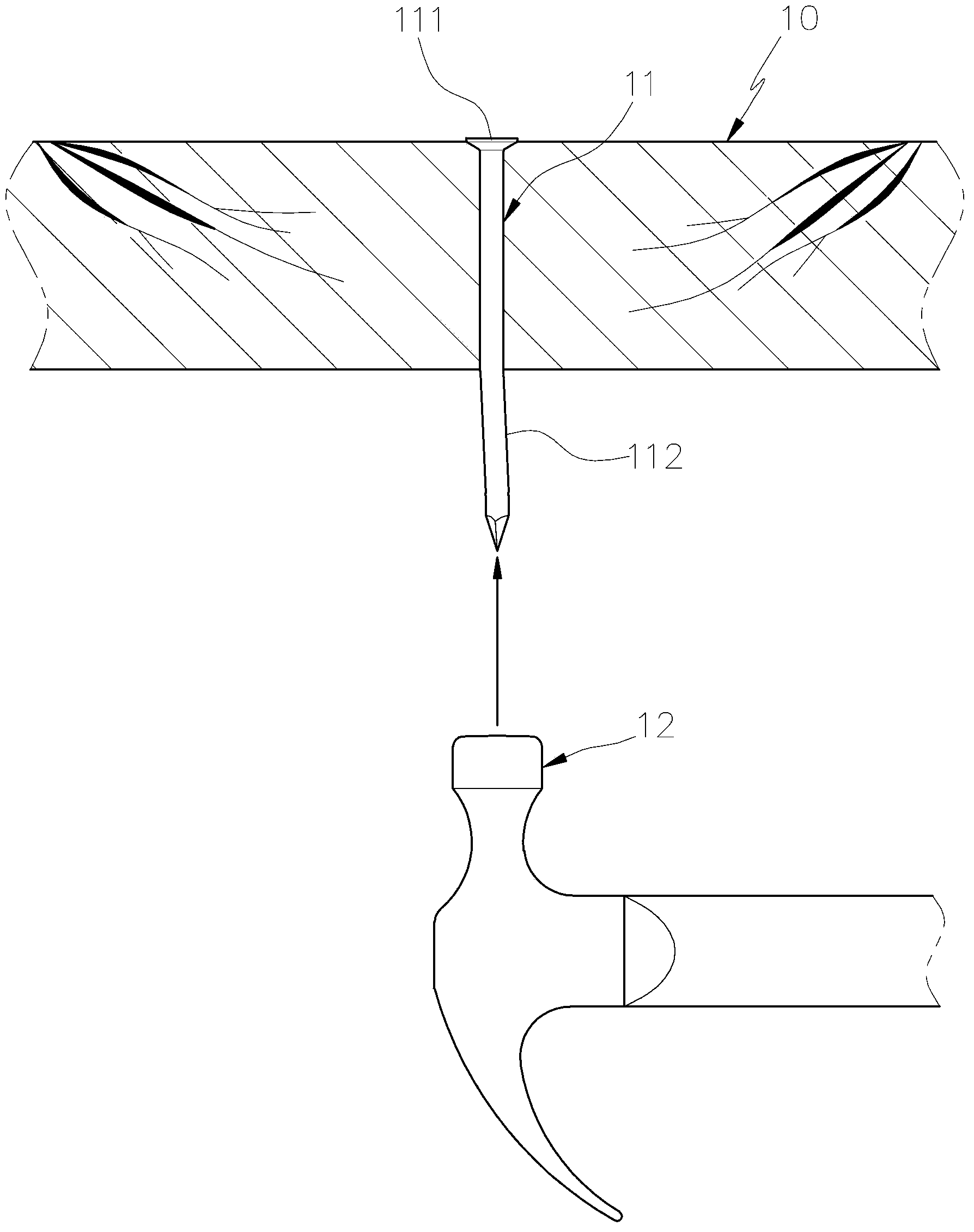
[0004] 2. When the hammer tool 12 hits the nail-in end 112 to make the nail 11 withdraw backward, because the nail-in end 112 is smaller than the head end 111, it is difficult for the hammer tool 12 to accurately hit the nail-in end 112
[0007] 1. The transparent holding tube 27 that polycarbonate resin is made, its material is more brittle, and can't penetrate the nail with it, and the nail is turned and straightened
[0008] 2. The rear end of the aluminum housing 21 is threadedly connected to the plug 24, and the rear end of the aluminum housing 21 is not suitable for strong knocking, and a strong knock will also damage the thread between the aluminum housing 21 and the plug 24, so only It is suitable for nailing with light hand pressure, and cannot be used as a nail ejector that requires strong knocking
[0009] 3. The rear end of the holding tube 27 is pushed against the plug 24 by the spring 31, and the handle 32 is moved forward, so that the shell 21 is on the outer periphery of the holding pipe 27, and the metal rod 26 slides on the inner periphery of the holding pipe 27. On the other hand, the holding pipe 27 can also slide on the inner periphery of the shell 21, that is, the connection relationship between the holding tube 27 and the shell 21 is a floating type. If it is used in the "nail remover" for strong knocking, the front end of the holding tube 27 cannot be powerful and stable. It is difficult to use as a nail ejector because it cannot provide the required force for strong knocking against the wall.

Method used


Image

  • Nail dismounting device
  • Nail dismounting device
  • Nail dismounting device

Examples


Embodiment Construction

[0047] In order to enable your examiner to have a further understanding of the present invention, hereby cite a preferred embodiment together with the accompanying drawings, and describe it in detail as follows:

[0048] see Image 6 , Figure 7 The nail remover 40 of the first embodiment of the present invention is provided with a hollow tubular outer casing 41 made of a high-hardness metal material. The hole 43 abuts against the tube base 42 and is integrated with the outer sleeve 41. A striking rod installed in the outer sleeve 41 has its first end stretched through the through sleeve hole 43 abutting against the tube base 42 with an appropriate length. , and make the through sleeve hole 43 reserve a receiving hole section 431, the second end of the striking rod protrudes from the outside of the second end of the outer casing 41; in this embodiment, the striking rod includes a first striking rod 44 And the second striking rod 45, the first end of the first striking rod 44...


PUM


Abstract

The invention discloses a nail dismounting device which is provided with a hollowly tubular outer sleeve and an impact rod, wherein a pressing pipe seat with a penetrating sleeve hole is fixedly arranged at the first end of the outer sleeve; the impact rod is arranged in the outer sleeve; the first end of the impact rod extends into the penetrating sleeve hole in the pressing pipe seat at a proper length, and a containing hole section is reserved in the penetrating sleeve hole; a middle rod body section of the impact rod is sleeved with an elastic element in a penetrating manner; one end of the elastic element is pressed against the pressing pipe seat, and the other end of the elastic element is pressed against a stage flange of the impact rod, so that the impact rod can be pressed on the elastic element to telescopically slide in the penetrating sleeve hole in the pressing pipe seat; the second end of the impact rod protrudes out of the second end of the outer sleeve to supply a knocking part; therefore, when needing to be dismounted from a plate, a bent nail can be contained in the containing hole section of the penetrating sleeve hole and then is rotated and straightened; then the impact rod is knocked to make the nail go back, so that the practical benefit of conveniently dismounting the nail from the plate can be achieved.

Description

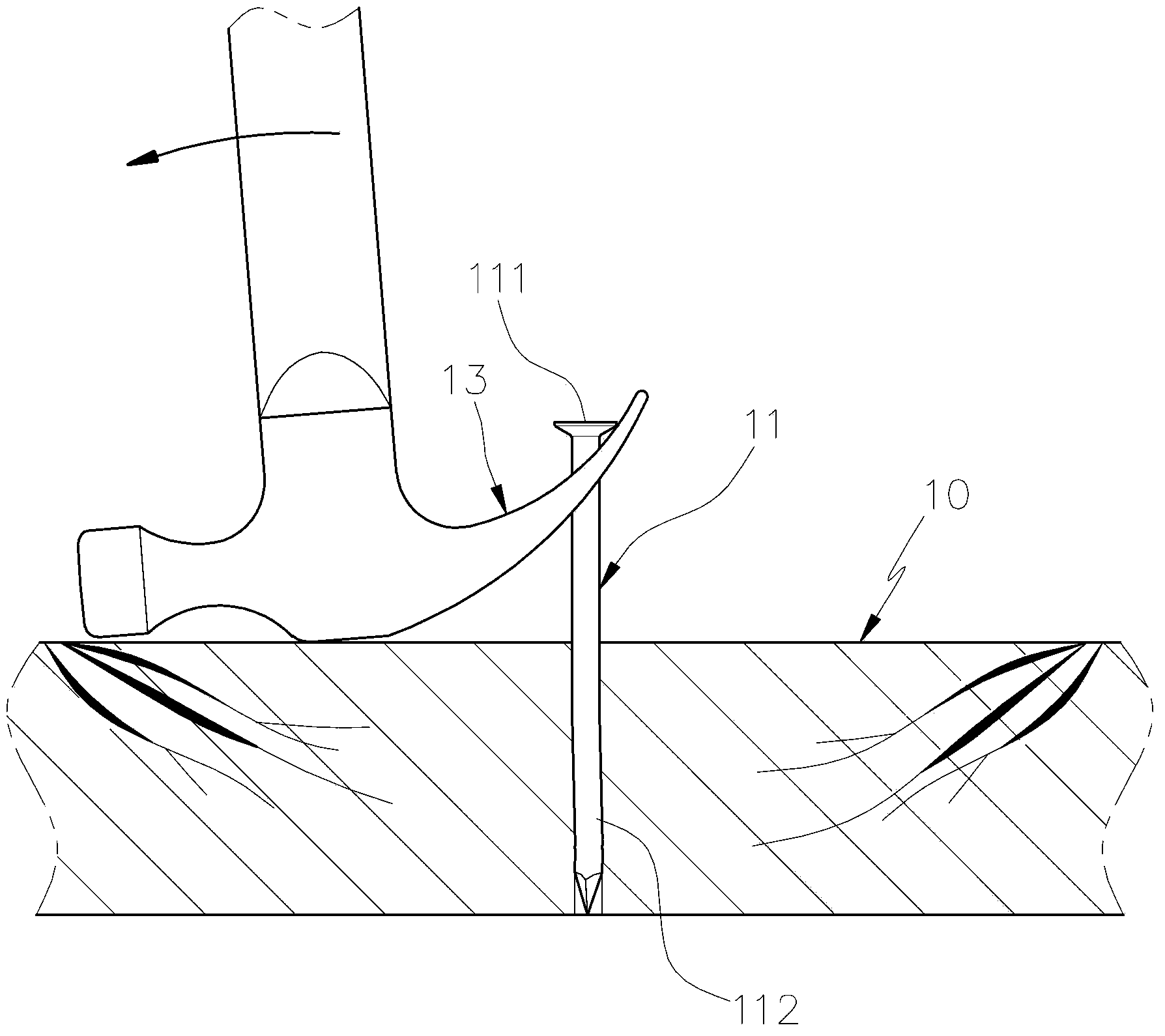
technical field [0001] The present invention relates to a plate dismantling tool, in particular to a nail remover capable of turning and straightening bent nails on a plate, and then knocking the nails back so as to facilitate the operation and removal of the nails. Background technique [0002] Nowadays, wooden boards are widely used, such as indoor wooden floors, decorative furniture, wooden pallets or building formwork, etc., are generally nailed with nails, but when the wooden boards are removed, they often appear on the boards. There are many protruding and bent nails left on the board. In order to avoid these nails from hurting the clearing personnel, the staff is often required to remove the nails on the board, especially the reusable building formwork, which is used every time After finishing, the remaining nails on the board must be removed. see figure 1 Generally, the bent nail 11 left on the wooden board 10 has its head end 111 still sticking to the board surfac...

Claims


Application Information

Patent Timeline
IPC IPC(8): B25C11/00B25C13/00
Inventor 施俊兆
Owner 施俊兆
Learn More