Piezoelectric power generating apparatus
A piezoelectric power generation and piezoelectric element technology, which is applied in the directions of generators/motors, piezoelectric/electrostrictive/magnetostrictive devices, piezoelectric effect/electrostrictive or magnetostrictive motors, etc. Space, occupation, etc.
- Summary
- Abstract
- Description
- Claims
- Application Information
AI Technical Summary
Problems solved by technology
Method used
Image


Examples
no. 1 Embodiment )
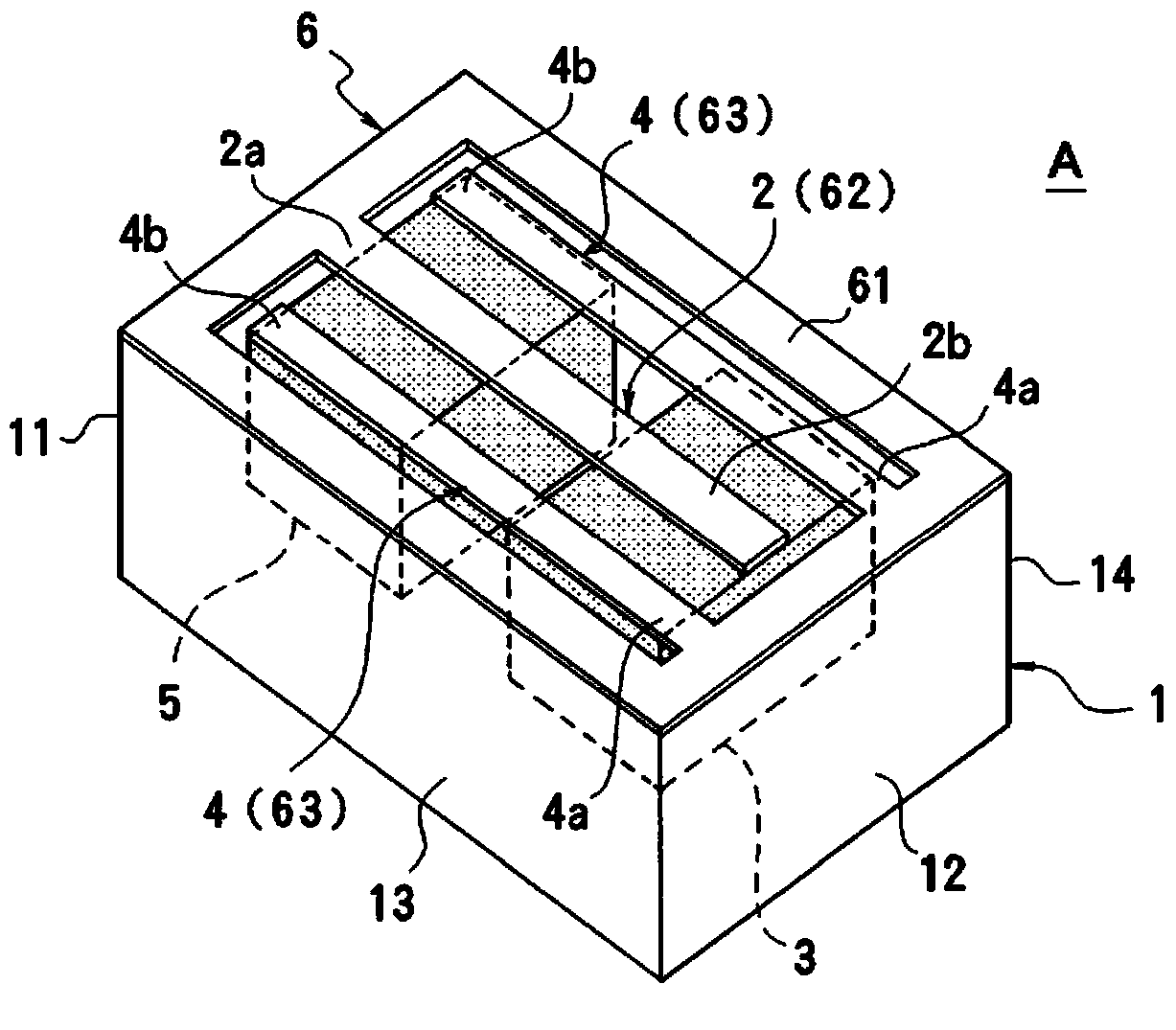
[0040] Figure 1 ~ Figure 3 A first embodiment of the piezoelectric generator according to the present invention is shown. The piezoelectric generator A of the present embodiment includes a box-shaped case 1 having four side wall portions 11 to 14 and a bottom wall portion 15, and is formed by the side wall portions 11 to 14 and the bottom wall portion 15. interior space16. Among the four side wall parts 11 to 14 of the casing 1 , the first and second side wall parts 11 and 12 of the two opposing side wall parts are the first fixing part and the second fixing part, respectively. In addition, a cover (not shown) is attached to the upper surface of the housing 1, and the inside of the housing 1 is sealed. The casing 1 is a fixing member in the present invention, and the side wall portion 11 and the side wall portion 12 are the first and second fixing parts in the present invention, respectively.
[0041] One end (fixed end) 2a of the first piezoelectric element 2 is fixed to ...
no. 2 Embodiment )
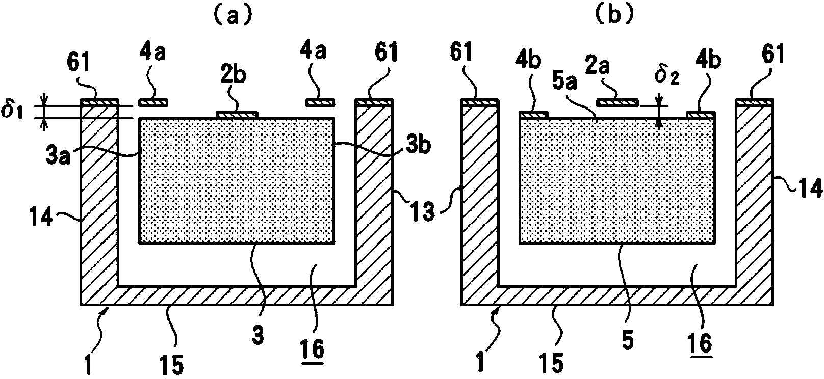
[0051] Figure 9 A second embodiment of the piezoelectric generator according to the present invention is shown. In the piezoelectric power generator B of this embodiment, the same reference numerals are assigned to the same parts as those of the first embodiment, and redundant descriptions will be omitted. Figure 9 (a) is with image 3 (a) A sectional view of the corresponding part, Figure 9 (b) is with image 3 (b) Cross-sectional view of the corresponding part. In this embodiment, a convex portion 3c is formed on the upper surface of the central portion of the first spindle 3, and stepped portions 3d, 3e that are one step lower are formed on both sides of the convex portion 3c. The convex part 3c of the first spindle 3 is fixed to the lower surface of the free end 2b of the first piezoelectric element 2, and the stepped parts 3d and 3e are arranged below the fixed end 4a side of the first piezoelectric element 4. On the other hand, convex portions 5b, 5c are formed o...
no. 3 Embodiment )
[0054] Figure 10 , Figure 11A third embodiment of the piezoelectric generator according to the present invention is shown. In the piezoelectric power generator C of the present embodiment, the same reference numerals are assigned to the same parts as those of the first embodiment, and redundant descriptions will be omitted. This embodiment differs from the first embodiment in that the first piezoelectric element is constituted by a pair of elements 2 and 2 . These first piezoelectric elements 2 , 2 are positioned between a pair of second piezoelectric elements 4 , 4 . The first spindle 3 is fixed to the free ends of the first piezoelectric elements 2, 2 so as to connect the free ends of the first piezoelectric elements 2, 2, and the widthwise end portions 3a, 3b of the first spindle 3 are The non-contact system is located below the fixed end side of the second piezoelectric elements 4 , 4 . The second spindle 5 is fixed to the free ends of the second piezoelectric elemen...
PUM
 Abstract
Description
Claims
Application Information
 - R&D
- Intellectual Property
- Life Sciences
- Materials
- Tech Scout
- Unparalleled Data Quality
- Higher Quality Content
- 60% Fewer Hallucinations
Browse by: Latest US Patents, China's latest patents, Technical Efficacy Thesaurus, Application Domain, Technology Topic, Popular Technical Reports.
© 2025 PatSnap. All rights reserved.Legal|Privacy policy|Modern Slavery Act Transparency Statement|Sitemap|About US| Contact US: help@patsnap.com