Single-person electric power operation auxiliary tool
A technology of electric power work and auxiliary tools, applied in the field of tools, can solve the problem of insufficient use of two hands
- Summary
- Abstract
- Description
- Claims
- Application Information
AI Technical Summary
Problems solved by technology
Method used
Image

Examples
Embodiment 1
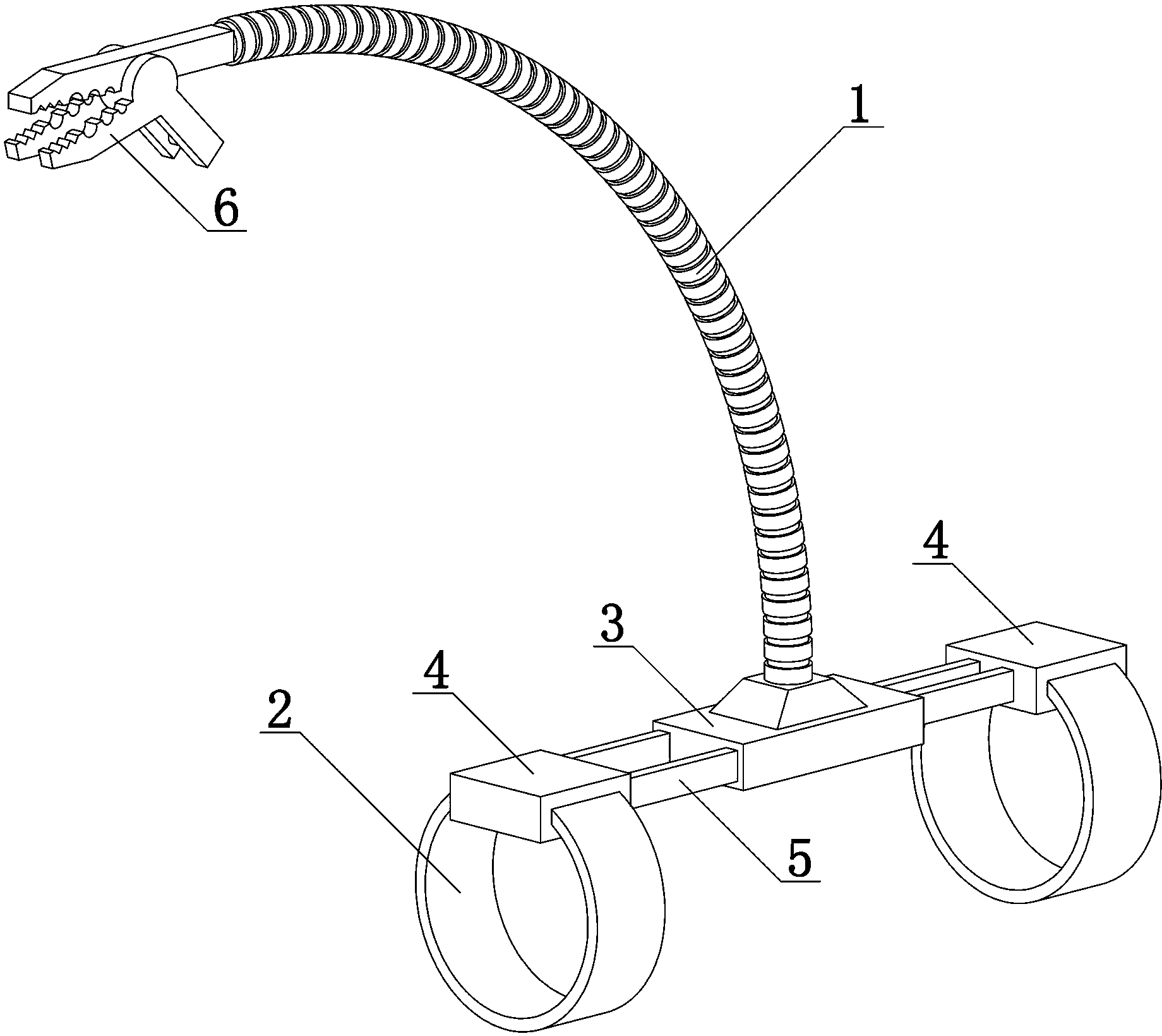
[0017] Such as figure 1 As shown, a single-person electrical work assisting tool includes an auxiliary arm 1 with arbitrarily curved and shaped structure, and fixing frames and tools respectively arranged at both ends of the auxiliary arm 1 , and the fixing frame is provided with a binding structure 2 . When in use, the fixing frame is fixed to the electric worker's arm through the binding structure 2, and then the auxiliary arm 1 is bent as required, so that the tool corresponds to the maintenance part of the electric equipment. In this way, the auxiliary arm 1 is equivalent to the third hand of the electric worker, and participates in the maintenance of electric equipment together with both hands of the electric worker. For example: when the tool is a lamp, it can assist lighting; when the tool is a clip, it can hold structures such as wires.
[0018] The auxiliary arm 1 is a metal shaped hose with an insulating jacket. The metal shaping hose can be bent into a certain sha...
Embodiment 2
[0020] The difference between Embodiment 2 and Embodiment 1 is that the fixed frame includes a main frame body 3 and two sub-frame bodies 4 respectively arranged on both sides of the main frame body 3, and the main frame body 3 is installed on the At one end of the auxiliary arm 1 , the binding structure 2 is installed on the sub-frame body 4 . The benefit of this design is: the binding structure 2 positioned on the sub-frame body 4 is easier to install and fix the whole fixture on the electrician's arm, and the auxiliary arm 1 is installed on the main frame body 3, so that The overall center of gravity of the fixed frame is relatively balanced, and it is not easy to slip or roll over.
[0021] Slots are respectively opened on both sides of the main frame body 3 , and insertion rods 5 are arranged on the sub-frame body 4 , and the insertion rods 5 are inserted and snapped into the slots. In the non-use state, the insertion rod 5 shrinks into the slot, effectively reducing the...
Embodiment 3
[0024] The difference between embodiment 3 and embodiment 2 is that: a clamping structure 6 is installed at one end of the auxiliary arm 1, and the clamping structure 6 clamps the tool. The advantage of this design is that some commonly used tools, such as flashlights and welding rods, can be conveniently clamped by using the clamping structure 6 .
PUM
 Abstract
Description
Claims
Application Information
 - Generate Ideas
- Intellectual Property
- Life Sciences
- Materials
- Tech Scout
- Unparalleled Data Quality
- Higher Quality Content
- 60% Fewer Hallucinations
Browse by: Latest US Patents, China's latest patents, Technical Efficacy Thesaurus, Application Domain, Technology Topic, Popular Technical Reports.
© 2025 PatSnap. All rights reserved.Legal|Privacy policy|Modern Slavery Act Transparency Statement|Sitemap|About US| Contact US: help@patsnap.com