Eureka AIR delivers breakthrough ideas for toughest innovation challenges, trusted by R&D personnel around the world.

Design method of unrestricted suspension type initiative gravity compensation system

A technology of gravity compensation and system design, which is applied in space navigation equipment, simulation devices of space navigation conditions, transportation and packaging, etc., can solve problems such as insufficient three-degree-of-freedom movement space, poor test results, and low compensation accuracy, and achieve Complete gravity compensation, small investment and high compensation accuracy

Active Publication Date: 2014-01-01
BEIHANG UNIV
View PDF3 Cites 74 Cited by
  • Summary
  • Abstract
  • Description
  • Claims
  • Application Information

AI Technical Summary

Problems solved by technology

The compensation accuracy of passive gravity compensation is low, which has a great impact on the test results; active gravity compensation can improve the compensation accuracy, but the current active gravity compensation method generally provides three degrees of freedom through single-point suspension or six degrees of freedom through multi-point suspension. Motion space, aiming at realizing the goal of spacecraft motion reproduction, three-degree-of-freedom motion space is obviously not enough. The six-degree-of-freedom space provided by multi-point suspension will lead to poor test results due to complex structure and difficult system control. Therefore, it is necessary to find a structure The simple, stable and fully compensated gravity compensation system provides the spacecraft with a microgravity environment that approximates unconstrained six-degree-of-freedom movement, and then reproduces its real movement in the space microgravity environment, ensuring ground verification of navigation, guidance and control systems the effectiveness of

Method used


Image

  • Design method of unrestricted suspension type initiative gravity compensation system
  • Design method of unrestricted suspension type initiative gravity compensation system
  • Design method of unrestricted suspension type initiative gravity compensation system

Examples


Embodiment Construction

[0035] The present invention will be further described below in conjunction with the accompanying drawings.

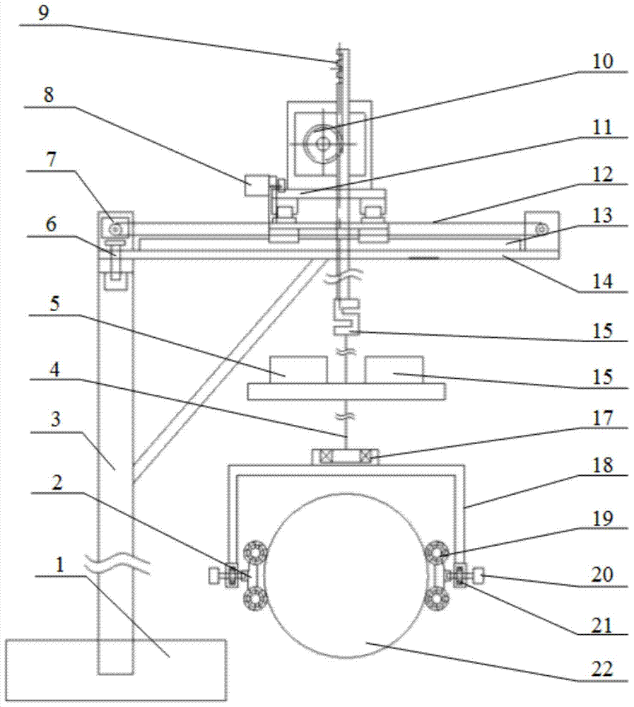
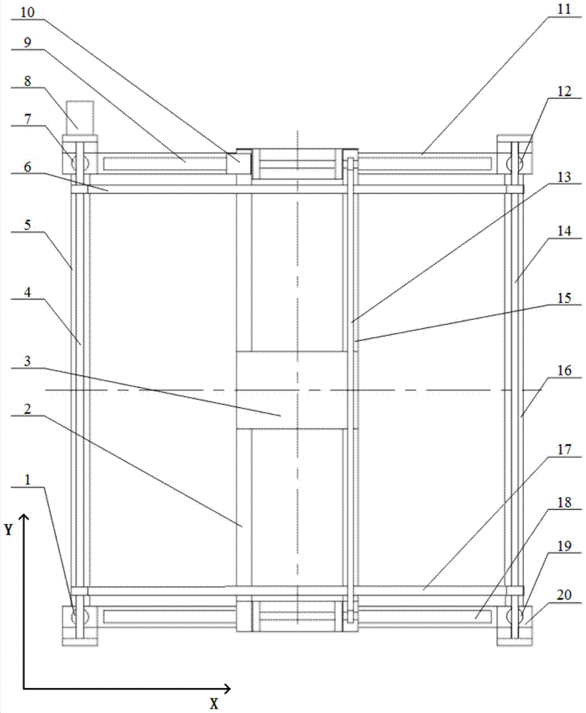
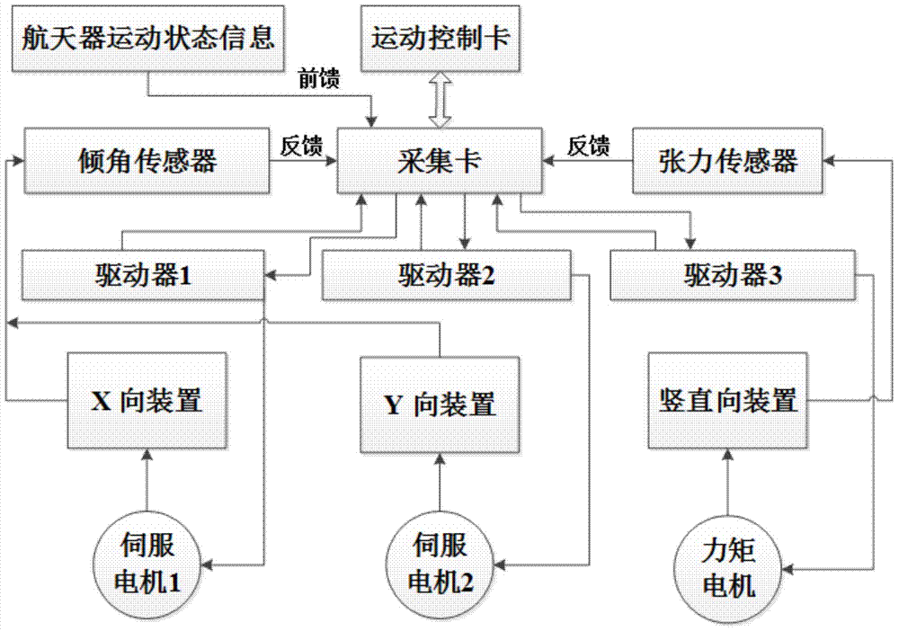
[0036] combine figure 1 , figure 2 , image 3 , the basic idea of ​​the present invention is to make the entire gravity compensation system not affect the three-degree-of-freedom attitude adjustment movement of the spacecraft itself through the unconstrained connection module, and to ensure that the suspension wire is in the vertical position during the movement of the spacecraft through the horizontal follow-up module and the corresponding control module. The vertical state does not generate horizontal interference force on the spacecraft. The vertical constant tension suspension module and the corresponding control module ensure that the tension of the suspension wire is always constant during the movement of the spacecraft, which can completely compensate the gravity of the spacecraft on the ground. Therefore, the goal of providing an approximate unconstrained si...


PUM


Abstract

Provided is an unrestricted suspension type initiative gravity compensation system. The system is composed of an unrestricted connecting module, a vertical constant tension suspension module, a horizontal follow-up module and a control module. The unrestricted connecting module comprises a connecting sleeve, an outer mounting frame, a force applying piece and a low friction bearing, and enables a spacecraft to carry out approximate unrestricted rotation round a center of mass. The vertical constant tension suspension module comprises a torque motor, a pinion and rack, a suspension hanging spring and a tension sensor, and enable the tensile force borne by the spacecraft in movement is equal to gravity. The horizontal follow-up module comprises a servo motor, a guide rail, a synchronous belt and a tilt angle sensor, and the suspension module is made to carry out horizontal movement along with the spacecraft to guarantee that the hanging spring is in a vertical state. The control module comprises an acquisition card, a driver and a motion control card. The design method of the unrestricted suspension type initiative gravity compensation system can compensate the gravity of the spacecraft in a ground test environment, further is used for reproducing the real movement of the spacecraft in the interspace microgravity environment, has the advantages of being stable in running, through in compensation and the like, and can provide the approximate unrestricted microgravity environment for movements with six degrees of freedom.

Description

Technical field [0001] The invention relates to the technical field of ground verification of spacecraft navigation, guidance and control systems, in particular to a design method for an unconstrained suspension active gravity compensation system for spacecraft motion reproduction. Background technique [0002] Aerospace engineering is a high-risk, high-investment, high-return, highly complex and high-precision system engineering. Its development level determines whether it can seize the high-tech commanding heights and maximize the use of space resources. There is no doubt that it is imminent to actively carry out aerospace technology research in our country. However, the space environment is extremely harsh. In order to successfully complete space missions, sufficient experiments must be carried out on the ground. Therefore, various space agencies at home and abroad attach great importance to the experimental verification of spacecraft on the ground. [0003] One of the mo...

Claims


Application Information

Patent Timeline
Patent Type & Authority Applications(China)
IPC IPC(8): B64G7/00
Inventor 贾英民孙施浩贾娇
Owner BEIHANG UNIV
Why Eureka
Eureka Blog
Learn More