Adjustable caterpillar track section clamping device

A technology of clamping device and chain rail joint, which is applied in the field of chain rail joint clamping, and can solve problems such as workpiece processing deformation

Inactive Publication Date: 2014-01-01
KUNSHAN KAINUOER METAL PROD
View PDF4 Cites 3 Cited by
  • Summary
  • Abstract
  • Description
  • Claims
  • Application Information

AI Technical Summary

Problems solved by technology

[0003] The purpose of the present invention is to provide an adjustable chain rail link clamping device to solve the problem of workpiece deformation caused by the traditional chain rail link clamping device

Method used


Image

  • Adjustable caterpillar track section clamping device

Examples


Embodiment Construction

[0017] The present invention will be further described in detail below in conjunction with the accompanying drawings and embodiments. It should be understood that the specific embodiments described here are only used to explain the present invention, but not to limit the present invention. In addition, it should be noted that, for the convenience of description, only some structures related to the present invention are shown in the drawings but not all structures.

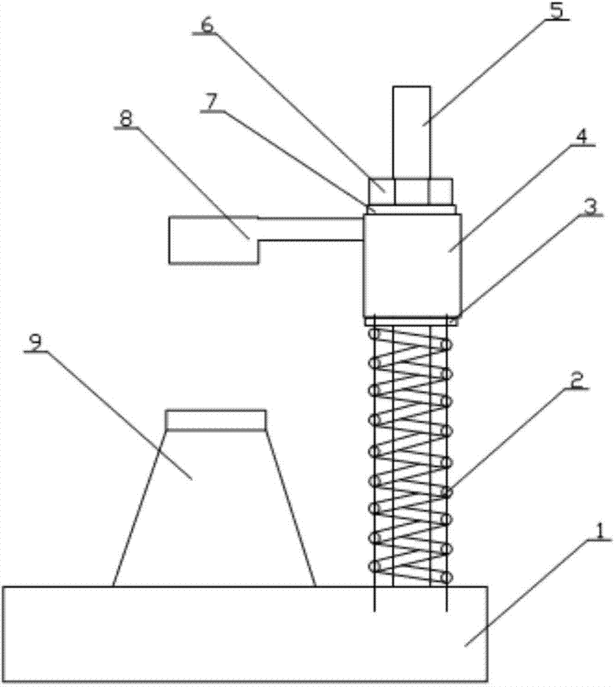
[0018] combine figure 1 The adjustable chain rail link clamping device of the present invention is described in detail.

[0019] The adjustable chain rail joint clamping device of the present invention includes a base 1, and also includes a spring 2, a support plate 3, a moving part 4, a support rod 5, a positioning nut 6, a gasket 7 and an upper pressing plate 8; the support rod 5 is set on the upper end of the base 1, the spring 2 is sleeved on the outside of the support rod 5, the support plate 3 is set on the...


PUM


Abstract

The invention relates to the technical field of caterpillar track section clamping, in particular to an adjustable caterpillar track section clamping device. The adjustable caterpillar track section clamping device comprises a base, a spring, a supporting plate, a movable part, a supporting rod, a locating nut, a spacer and an upper pressing plate. The supporting rod is arranged at the upper end of the base, the supporting rod is sleeved with the spring, the supporting plate is arranged at the upper end of the spring, the movable part is arranged at the upper end of the supporting plate, the locating nut is arranged on the supporting rod and presses the movable part through the spacer, and the upper pressing plate is arranged on one side of the movable part and directly faces the base. The locating nut is adjusted to enable the movable part to drive the upper pressing plate to move downwards to press a work-piece. The spring supports the movable part through the supporting plate so that appropriate clamping force can be exerted on the work-piece, and the work-piece is protected against deformation caused by the excessively large or small clamping force.

Description

technical field [0001] The invention relates to the technical field of chain rail link clamping, in particular to an adjustable chain rail link clamping device. Background technique [0002] At present, the general clamping device used for processing chain rail links adopts the method of directly clamping the workpiece by the oil cylinder, and the clamping force directly acts on the workpiece. Vibration causes processing deformation; if the clamping force of the oil cylinder is too large, the workpiece will be clamped and deformed, which will eventually lead to processing deformation. The above two situations will lead to low machining accuracy or even scrapping of workpieces, resulting in waste and reduced production efficiency. Contents of the invention [0003] The object of the present invention is to provide an adjustable chain rail link clamping device, which solves the problem that the traditional chain rail link clamping device causes workpiece deformation. [00...

Claims


Application Information

Patent Timeline
Patent Type & Authority Applications(China)
IPC IPC(8): B25B11/00
CPCB21L19/00B25B11/00
Inventor 戎海明
Owner KUNSHAN KAINUOER METAL PROD
Why Eureka
Try Eureka