
Voltage source type asymmetric pulse converter and output pulse control method thereof

A pulse conversion and voltage source technology, applied in the field of power electronics, can solve the problems of small application range and single pulse form

Inactive Publication Date: 2013-12-25
XIAN UNIV OF TECH
View PDF6 Cites 4 Cited by
  • Summary
  • Abstract
  • Description
  • Claims
  • Application Information

AI Technical Summary

Problems solved by technology

[0005] The purpose of the present invention is to provide a voltage source type asymmetric pulse converter, which solves the problem of single pulse form and small application range in the prior art

Method used

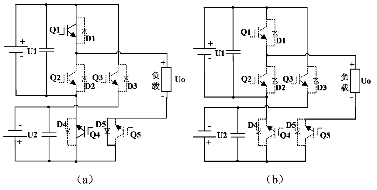
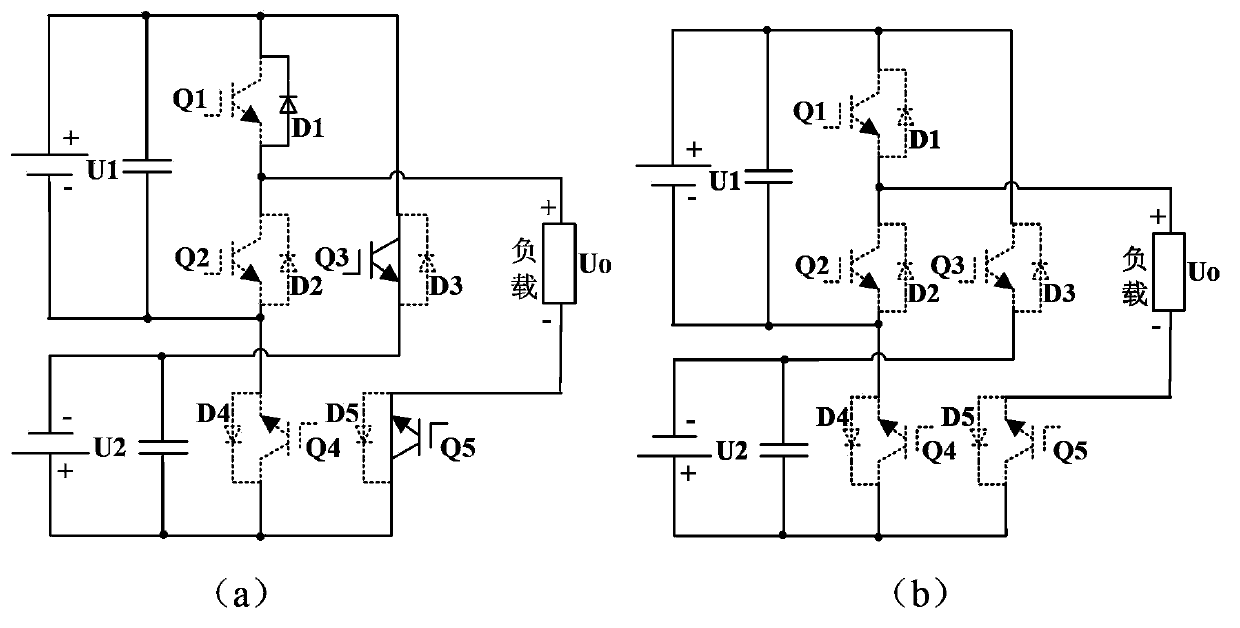

Image

  • Voltage source type asymmetric pulse converter and output pulse control method thereof
  • Voltage source type asymmetric pulse converter and output pulse control method thereof
  • Voltage source type asymmetric pulse converter and output pulse control method thereof

Examples


Embodiment Construction

[0050] The present invention will be further described below in conjunction with accompanying drawing.

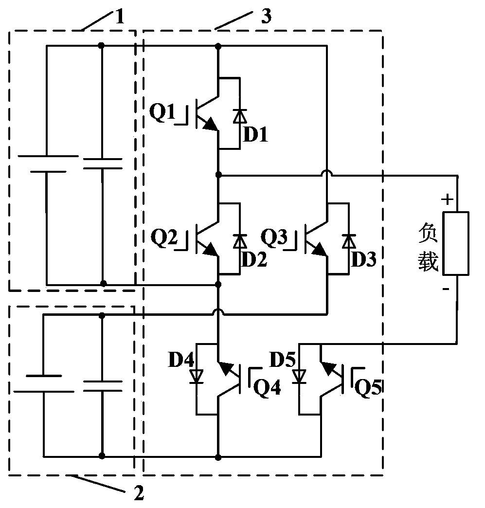
[0051] The present invention provides a voltage source type asymmetric pulse converter, such as figure 1 As shown, it includes a first DC voltage source 1, a second DC voltage source 2, and a pulse converter circuit 3, wherein the pulse converter circuit 3 includes a switching tube Q 1 , switch tube Q 2 , switch tube Q 3 , switch tube Q 4 , switch tube Q 5 , Diode D 1 , Diode D 2 , Diode D 3 , Diode D 4 , Diode D 5 , its circuit structure is:

[0052] The anode of the first DC voltage source 1 is respectively connected to the switching tube Q 1 and switch Q 3 The collector of the first DC voltage source 1 is connected to the negative pole of the switch tube Q 2 The emitter of the second DC voltage source 2 is connected to the negative pole of the switch tube Q 3 The emitter of the second DC voltage source 2 is connected with the positive pole of the switch tube...


PUM


Abstract

The invention discloses a voltage source type asymmetric pulse converter and belongs to the field of an electrical and electronic converter. The converter comprises a first DC voltage source, a second DC voltage source and a pulse converter circuit. The pulse converter circuit is composed of five switch tubes and five diodes. The invention also discloses an output pulse control method by using the pulse converter. According to the invention, two DC voltage sources are utilized as an input, the pulse converter circuit is composed of the five tube switches and the five diodes so that multiple pulse output can be realized through control over the conduction of the switch tubes. Besides, the structure is simple, the control is convenient, and the disadvantages of single output pulse form and narrow application scope of a conventional pulse converter can be overcome.

Description

technical field [0001] The invention belongs to the technical field of power electronics, and in particular relates to a voltage source type asymmetric pulse converter, and also relates to a control method for outputting pulses by using the above pulse converter. Background technique [0002] In recent years, pulse power supply has been more and more widely used in electroplating, environmental protection, welding, vacuum coating, EDM and other fields, especially in some special occasions, the advantages of pulse power supply are becoming more and more obvious, such as micro-arc oxidation pulse power supply , Magnetron sputtering pulse power supply, arc welding pulse power supply, etc. [0003] At present, most of the pulses generated by pulse converters used in pulse power supplies are unidirectional pulses or simple bidirectional pulses, and only a few of them can generate more complex pulses. For example, the patent publication number is: CN101125389, and the publication ...

Claims


Application Information

Patent Timeline
IPC IPC(8): H02M9/02
Inventor 陈桂涛孙天乐孙强黄西平
Owner XIAN UNIV OF TECH
Learn More