
Magnet ring component

A component and magnetic ring technology, applied in the field of magnetic ring components, can solve problems such as winding difficulties

Inactive Publication Date: 2013-12-25
KUNSHAN YOUXIANG ELECTRONICS SCI & TECH
View PDF6 Cites 4 Cited by
  • Summary
  • Abstract
  • Description
  • Claims
  • Application Information

AI Technical Summary

Problems solved by technology

The magnetic ring needs to be wound, and the existing thick magnetic wire can only be wound by hand, but it is difficult to wind the complete circular magnetic ring

Method used


Image

  • Magnet ring component
  • Magnet ring component

Examples


Embodiment Construction

[0015] The present invention will be specifically introduced below in conjunction with the accompanying drawings and specific embodiments.

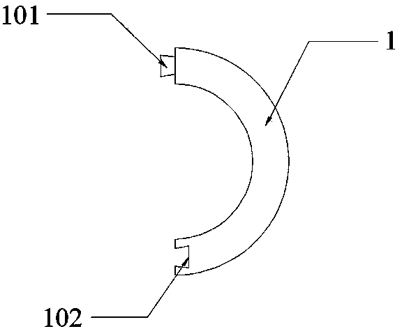
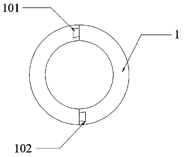
[0016] Such as figure 1 , 2 The magnetic ring assembly shown includes two semi-circular connecting pieces 1, one end of the connecting piece 1 has a raised clamping part 101, and the other end of the connecting piece 1 is provided with a concave interface part matched with the clamping part 101 102. The cross-section of the clamping part 101 in the axial direction of the connector 1 is trapezoidal, and the upper bottom of the trapezoid is connected to the connector 1; edge contact. The locking part 101 and the interface part 102 have the same shape and the same size. It is convenient for batch processing, and can make the clamping part 101 of one connecting part snap into the interface part 102 of another connecting part.

[0017] The axial length of the engaging part 101 and the interface part 102 along the connecting part 1 is equa...


PUM


Abstract

The invention discloses a magnet ring component comprising two semicircular connectors. The magnet ring component is characterized in that one end of each connector is provided with a projecting fastener part, the other end of each connector is provided with a concave groove part fitting the fastener part, the axial section of each fastener part, on the connector, is trapezoid shaped, a topline of each trapezoid is connected with the corresponding connector, the axial section of each groove part, on the connector, is also trapezoid shaped, and a topline of each trapezoid contacts with the edge of the corresponding connector. The magnet ring component has the advantages that the magnet ring is split during winding into two independent semicircular connectors respectively used for winding; after winding, the connectors are combined into the complete magnet ring by means of axial sliding; winding is easier and more efficient.

Description

technical field [0001] The invention relates to a magnetic ring, in particular to a magnetic ring assembly. Background technique [0002] The magnetic ring is an anti-interference component commonly used in electronic circuits. It has a good suppression effect on high-frequency noise and is generally made of ferrite materials (Mn-Zn). The magnetic ring has different impedance characteristics at different frequencies. Generally, the impedance is very small at low frequencies. When the signal frequency increases, the impedance of the magnetic ring increases sharply. A wire needs to be wound on the magnetic ring, and the existing thick magnetic wire can only be wound by hand, and it is difficult to wind the wire on a complete circular magnetic ring. Contents of the invention [0003] In order to solve the deficiencies of the prior art, the purpose of the present invention is to facilitate the disassembly of the magnetic ring wound. [0004] In order to achieve the above obj...

Claims


Application Information

Patent Timeline
Patent Type & Authority Applications(China)
IPC IPC(8): H01F7/00H01F27/24H01F41/02
Inventor 任育文
Owner KUNSHAN YOUXIANG ELECTRONICS SCI & TECH
Learn More