Eureka AIR delivers breakthrough ideas for toughest innovation challenges, trusted by R&D personnel around the world.

Energy recovery device using deceleration strip

A technology of energy recovery devices and speed bumps, which is applied to roads, machines/engines, road signs, etc., can solve the problems of restricting product marketization, high cost of road space reconstruction, complex structure, etc., and achieve high operability and adaptability , Strengthen the deceleration warning function, the effect of high energy conversion rate

Inactive Publication Date: 2013-12-25
DONGHUA UNIV
View PDF5 Cites 18 Cited by
  • Summary
  • Abstract
  • Description
  • Claims
  • Application Information

AI Technical Summary

Problems solved by technology

[0005] 1. The structure is relatively complex and the number of parts is large
As we all know, energy transmission consumes energy. The more complex the structure and the more transmission steps, the more energy will be lost in the process of energy collection. Moreover, the complexity of the structure will increase the production cost and restrict the marketization of products.
On the other hand, due to the complexity of the mechanism, the volume of the device will inevitably increase, and due to the limited space under the speed bump, it will require a large cost to transform the road space, thus restricting the application of this type of invention
[0006] 2. Lack of protection for the device
[0007] 3. The energy release process is unstable

Method used


Image

  • Energy recovery device using deceleration strip
  • Energy recovery device using deceleration strip
  • Energy recovery device using deceleration strip

Examples


Embodiment Construction

[0022] Below in conjunction with specific embodiment, further illustrate the present invention. It should be understood that these examples are only used to illustrate the present invention and are not intended to limit the scope of the present invention. In addition, it should be understood that after reading the teachings of the present invention, those skilled in the art can make various changes or modifications to the present invention, and these equivalent forms also fall within the scope defined by the appended claims of the present application.

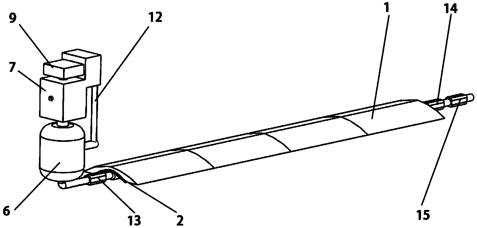
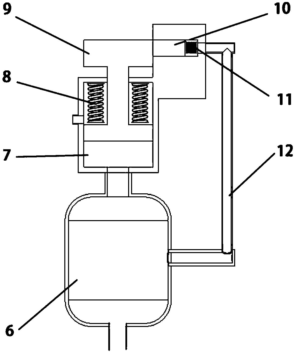
[0023] The present invention consists of figure 2 shown in the energy harvesting section and as image 3 The shown energy stable release part consists of two parts. Assembly as figure 1 shown in the general assembly drawing.

[0024] The function of the energy collection part is to convert the mechanical energy generated when the car passes through the speed bump into gas pressure energy, and transmit it to the energy stab...


PUM


Abstract

The invention relates to an energy recovery device using a deceleration strip. The energy recovery device comprises an energy collecting part and an energy stably-releasing part, wherein the energy collecting part comprises the deceleration strip arranged on the ground through a spring; a strip-shaped air bag is assembled below the deceleration strip in a hollowed way; the deceleration strip and the air bag are connected with each other through a pair of pressure plates for transmission; the pressure plates are connected with the ground through a hinge; a pneumatic one-way valve is connected to the two ends of the air bag respectively; the one-way valve on one air outlet side is connected with the energy stably-releasing part. According to the energy recovery device, energy can be collected and released stably, and an appropriate device is provided for protecting a road deceleration strip generating set of a system.

Description

technical field [0001] The invention relates to an energy recovery device, in particular to an energy recovery device using a speed bump. Background technique [0002] Speed ​​bumps are also called speed bumps, which are traffic facilities installed on the road to slow down passing vehicles. They are generally yellow and black to attract visual attention, and the road surface is slightly arched to achieve the purpose of vehicle deceleration. They are usually installed at road crossings, industrial and mining enterprises Road sections that require vehicles to slow down and road sections that are likely to cause traffic accidents, such as roads, schools, and residential complex entrances, are new traffic-specific safety settings used to slow down the speed of motor vehicles and non-motor vehicles. The speed bump has greatly reduced the occurrence of accidents at major traffic intersections, and is a new type of special facility for traffic safety. The vehicle is not only safe...

Claims


Application Information

Patent Timeline
IPC IPC(8): F03G3/00E01F9/047E01F9/529
Inventor 唐智陈雯周申华刘志辉石熠沈伟斌杨帅
Owner DONGHUA UNIV
Why Eureka
Eureka Blog
Learn More