
Large-displacement railroad bridge end expansion device

A telescopic device and large displacement technology, used in bridges, bridge parts, bridge construction, etc., can solve problems such as inability to meet use requirements, weak structural bearing capacity, and inability to meet less maintenance requirements, and meet the requirements of train running. Roughness, the effect of increasing the vertical and lateral bending stiffness

Active Publication Date: 2013-12-25
BEIJING TIEKE SPECIAL ENG TECH CO LTD +2
View PDF5 Cites 7 Cited by
  • Summary
  • Abstract
  • Description
  • Claims
  • Application Information

AI Technical Summary

Problems solved by technology

[0006] This kind of large-displacement beam end telescopic device bears the train load through the cantilever middle leg protruding from the beam end. Due to the limitation of the section characteristics of the middle leg and the length of the cantilever, the structure has a weak bearing capacity, so it is used for large displacement and heavy load railways. The safety of the bridge is poor; at the same time, this kind of structure only has two variable joints, limited by the specification that the sleeper spacing does not exceed 650mm, the variable joint width is between 20mm and 320mm, and the adaptable beam end displacement is less than ± 300mm, for railway bridges whose beam end displacement exceeds ±300mm, it cannot meet the requirements for use; in addition, main components such as supporting beams and bearing supports are located at the lower part of sleepers. When a disease occurs, it is necessary to set up an auxiliary platform on the pier for disease treatment. Therefore, this structure does not meet the requirements of less maintenance and easy inspection.

Method used


Image

  • Large-displacement railroad bridge end expansion device
  • Large-displacement railroad bridge end expansion device
  • Large-displacement railroad bridge end expansion device

Examples


Embodiment Construction

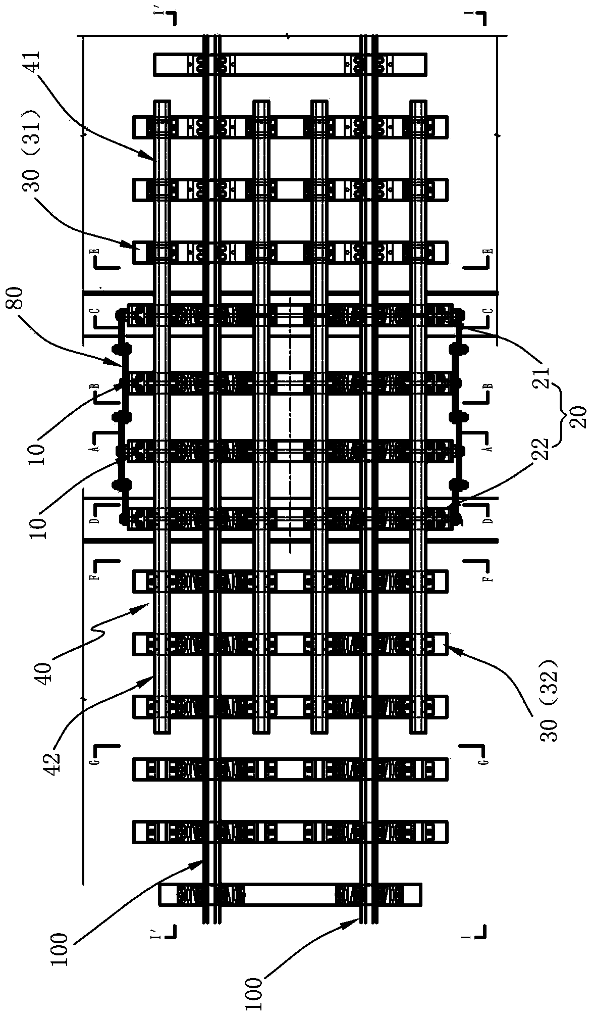
[0070] The present invention proposes a large-displacement railway bridge beam end telescopic device, comprising: concrete sleepers arranged on adjacent first bridges and second bridges; fixed steel sleepers respectively installed at the corresponding beam ends of the two bridges There are first fixed steel sleepers and second fixed steel sleepers; supporting beams, above the concrete sleepers and fixed steel sleepers, four supporting beams are arranged along the length direction of the rail, one end of the supporting beams is a fixed end, and the other end is a The movable end, the fixed end is fixedly connected with the first concrete sleeper and the first fixed steel sleeper arranged on the first bridge, and the movable end is connected with the second concrete sleeper and the second concrete sleeper arranged on the second bridge. The fixed steel sleepers are connected flexibly; at least one movable steel sleeper is arranged between the first bridge and the second bridge and...


PUM


Abstract

The invention relates to a large-displacement railroad bridge end expansion device, which comprises concrete sleepers, fixed steel sleepers, four support beams and at least one movable steel sleeper, wherein the concrete sleepers are arranged on adjacent first bridge and second bridge; the first fixed steel sleeper and the second fixed steel sleeper are respectively arranged on the corresponding bridge ends of the two bridges; the four support beams are arranged above the concrete sleepers and the fixed steel sleepers along the steel rail length direction; one end of each support beam is a fixed end, and the other end of the support beam is a movable end; the fixed ends are fixedly connected with the first concrete sleeper and the first fixed steel sleeper arranged on the first bridge; the movable ends are movably connected with the second concrete sleeper and the second fixed steel sleeper arranged on the second bridge; and the movable steel sleeper is arranged between the first bridge and the second bridge and is connected with the bottoms of the support beams. The support beams of the large-displacement railroad bridge end expansion device disclosed by the invention are arranged above the fixed steel sleepers and the movable steel sleepers to overcome the defects existing in the prior art, and the large-displacement railroad bridge end expansion device has the advantages of simple structure and easiness in line inspection.

Description

technical field [0001] The invention relates to a telescoping device, in particular to a telescoping device for a beam end of a large-displacement railway bridge. Under the action of temperature changes and train live loads, the girder body of long-span railway bridges will have a large displacement at the girder end of the adjacent bridge or between the bridge and the abutment. In order to maintain the continuity of the bridge and the track, the adjacent bridge end range The beam end telescopic device of the present invention is arranged inside to meet the requirements of train operation. Background technique [0002] The expansion device at the beam end of the railway bridge is installed at the gap between the beams to ensure the reliable transition and support of the rail at the gap between adjacent bridges. Since the expansion device is arranged at the most unfavorable position of the bridge, its performance is very important. First, the telescopic device at the beam en...

Claims


Application Information

Patent Timeline
IPC IPC(8): E01D19/06E01D19/12
Inventor 臧晓秋胡所亭石秋君佟嘉明张士臣
Owner BEIJING TIEKE SPECIAL ENG TECH CO LTD
Learn More