Pipe pressing device for galvanizing machine
A technology of pressing tubes and pressing plates, which is applied in hot-dip galvanizing process, metal material coating process, coating, etc., which can solve problems such as jamming, bending of steel pipes, floating steel pipes, etc., and achieves convenient disassembly and replacement of components and long service life Long and easy to install
- Summary
- Abstract
- Description
- Claims
- Application Information
AI Technical Summary
Problems solved by technology
Method used
Image
Examples
Embodiment 1
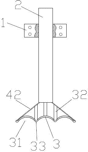
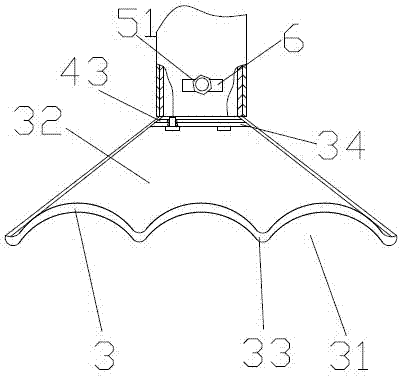
[0034] A pipe pressing device for a galvanizing machine, comprising a guide sliding sleeve 1, a pressing rod 2 provided on the guiding sliding sleeve 1 and capable of moving up and down along the guiding sliding sleeve 1, a pressing plate part arranged at the bottom end of the pressing rod 2 and connecting The power part at the top of the pressure rod 2. The pressure plate component includes a pressure plate seat connected to the bottom end of the pressure rod 2 and a pressure plate 3 arranged at the bottom of the pressure plate seat. The pressure plate 3 is concavely formed with several pressure plate grooves 31 with arc-shaped cross-sections and arranged in parallel. The arc-shaped transition section passes between the pressure plate grooves 31 33 connections.
[0035] The pressure plate seat includes two inclined and symmetrically arranged side plates 42 , the angle between the side plates 42 is 100 degrees, and the bottom ends of the two side plates 42 are respectively con...
Embodiment 2
[0037] The difference from the above embodiment is that the pressing plate part and the pressing bar are detachably connected, and there are three pressing plate grooves 31 . The notch span of the pressing plate groove 31 is 25mm, and the groove depth is 10mm. The angle between the side plates 42 is 120 degrees
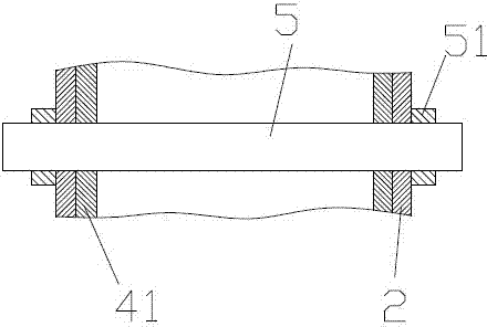
[0038] A connecting rod 41 for connecting the pressing rod 2 is arranged on the top of the pressing plate seat, and the connecting rod 41 is detachably sleeved on the pressing rod 2 . The connecting rod 41 is connected with the pressing rod 2 through the insertion rod 5 passing through the connecting rod 41 and the pressing rod 2 transversely, and the two ends of the insertion rod 5 are provided with fixing parts 51 . There are external threads at both ends of the insertion rod, and the fixing part is a nut matched with the external threads. The connecting rod 41 or the pressing rod 2 is provided with an in-line adjustment hole 6 for passing through the insertion ro...
Embodiment 3
[0040] The difference from the above embodiment is that the top of the side plate 42 is connected by the top plate 43 , the reinforced support member 32 is a reinforced support plate, and the top of the reinforced support plate is provided with a connecting plate 34 detachably connected to the top plate 43 . The connecting plate is detachably connected with the top plate through bolts. The pressure plate is easy to replace and disassemble. The pressing plate 3 is provided with six pressing plate grooves 31, the span of the openings of the pressing plate grooves 31 is 30 mm, and the groove depth is 15 mm. The angle between the side plates 42 is 130 degrees
[0041] A pipe pressing device is installed on the galvanizing pool, so that the rear end of the steel pipe with an outer diameter of 20-22 mm and a wall thickness of 1.6 mm or less is smoothly pressed down after galvanizing, and there is still a large amount of air in the lumen. The inclination angle of the steel pipe is ...
PUM
| Property | Measurement | Unit |
|---|---|---|
| angle | aaaaa | aaaaa |
| thickness | aaaaa | aaaaa |
Abstract
Description
Claims
Application Information
 - R&D
- Intellectual Property
- Life Sciences
- Materials
- Tech Scout
- Unparalleled Data Quality
- Higher Quality Content
- 60% Fewer Hallucinations
Browse by: Latest US Patents, China's latest patents, Technical Efficacy Thesaurus, Application Domain, Technology Topic, Popular Technical Reports.
© 2025 PatSnap. All rights reserved.Legal|Privacy policy|Modern Slavery Act Transparency Statement|Sitemap|About US| Contact US: help@patsnap.com


