
Ultrasonic flow rate measurement device

A flow measurement and ultrasonic technology, which is applied in the field of ultrasonic flow measurement devices, can solve the problems of increased man-hours, difficulty in reducing power consumption, and material costs.

Active Publication Date: 2013-12-18
PANASONIC CORP
View PDF9 Cites 7 Cited by
  • Summary
  • Abstract
  • Description
  • Claims
  • Application Information

AI Technical Summary

Problems solved by technology

As a result, the turbulent flow of the fluid to be measured at the measurement portion (propagation path of ultrasonic waves) of the flow measuring tube 121 and the concave portions 125a, 125b is reduced, and the deterioration of measurement accuracy is reduced.
However, since other components are required, there is a problem that the cost increases due to the increase in material costs and man-hours
[0008] In addition, since the reception level of ultrasonic waves in the ultrasonic sensors 122a and 122b decreases, there is a problem that it is difficult to reduce the drive input of the ultrasonic sensors 122a and 122b.
Therefore, like a gas meter for measuring domestic gas such as city gas and LPG (Liquefied petroleum gas: liquefied petroleum gas), it is difficult to continue using it for a long time such as 10 years with a small battery capacity. low power consumption

Method used


Image

  • Ultrasonic flow rate measurement device
  • Ultrasonic flow rate measurement device
  • Ultrasonic flow rate measurement device

Examples


no. 1 approach

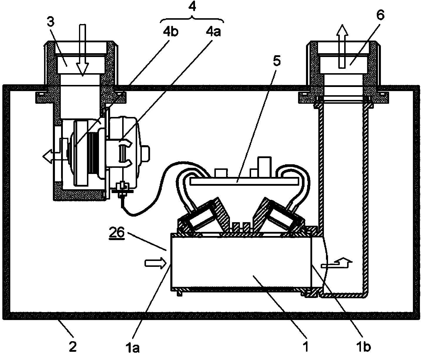
[0031] figure 1 It is a cross-sectional view showing the structure of the ultrasonic flow rate measuring device 50 in the embodiment of the present invention. figure 1 The hollow arrow indicates the flow of fluid (fluid to be measured).

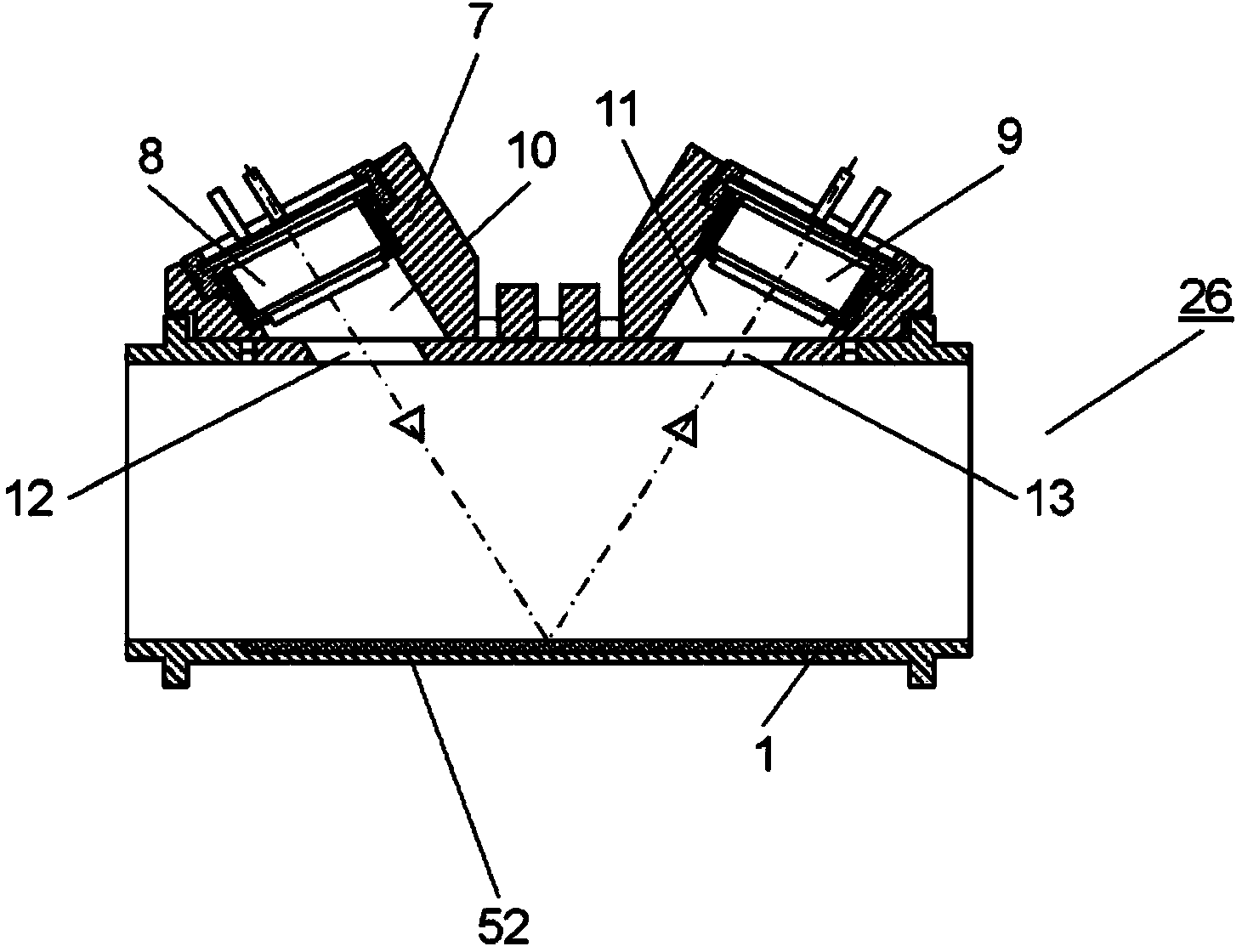
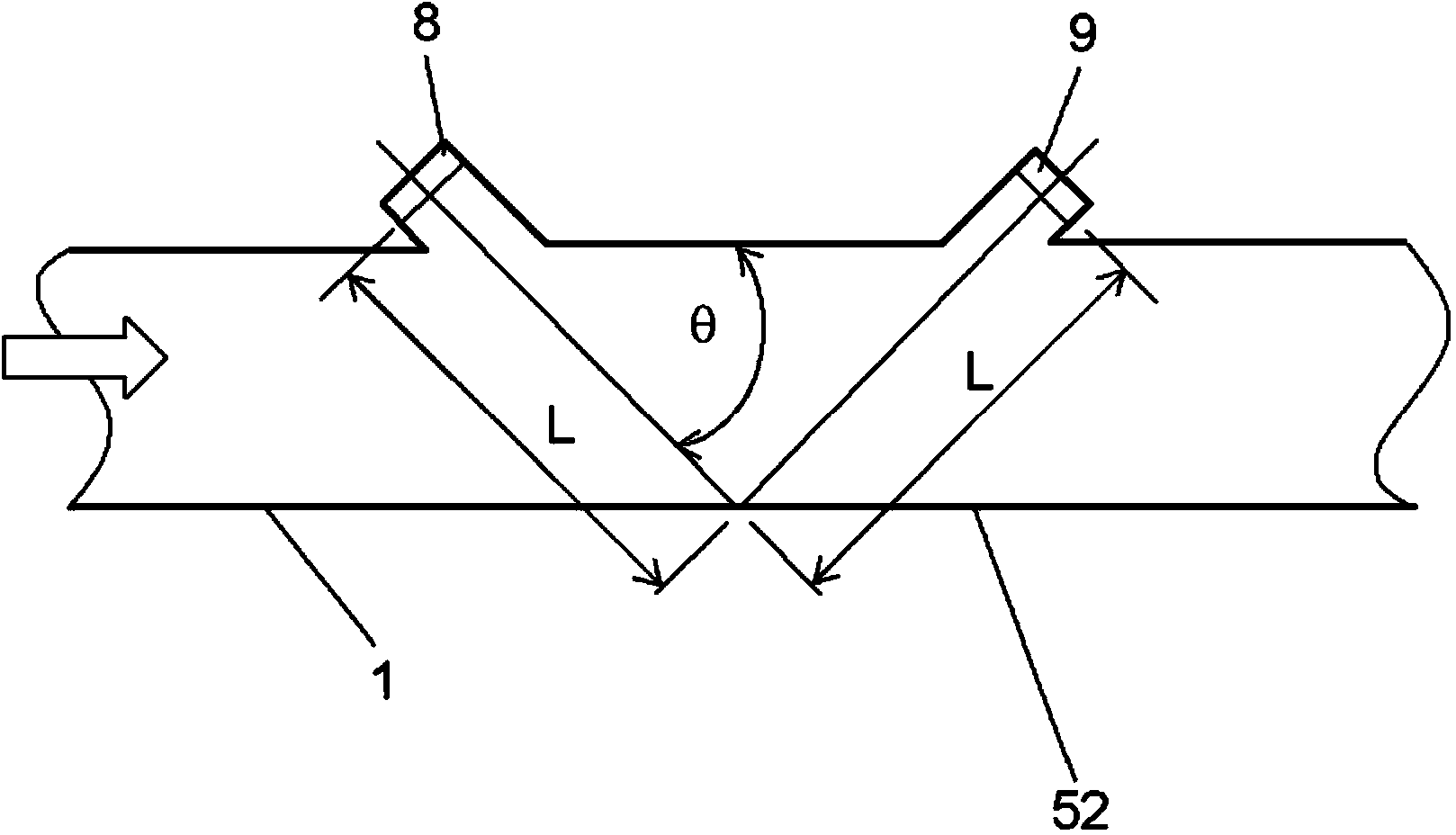
[0032] Such as figure 1 As shown, the ultrasonic flow rate measuring device 50 includes a fluid supply path 3. The fluid supply path 3 has a shut-off valve 4 in the middle of the flow path. The shut-off valve 4 includes a drive portion 4a and a valve body 4b that cooperates with the drive portion 4a, and is opened and closed by the valve body 4b, wherein the drive portion 4a includes a step Into electromagnetic devices such as motors. In a state where the shutoff valve 4 is open, the fluid to be measured flows out of the fluid supply path 3 into the inside of the measuring instrument housing 2. The ultrasonic flow rate measurement device 50 includes a measurement flow path 1 through which a fluid to be measured flows. The measurement flow p...

no. 2 approach

[0069] Picture 11 It is a perspective view showing the structure of the slide mold 32 in the second embodiment of the present invention. Picture 12 It is a perspective view showing the structure of the sensor mounting housing 7 in the second embodiment of the present invention.

[0070] The structures of the ultrasonic flow rate measuring device 50 and the mold in this embodiment are the same as those of the first embodiment except for the structure of the slide mold 32, so the description thereof is omitted.

[0071] In this embodiment, as Picture 11 As shown, a grid-shaped groove 33 is formed at the front end of the sliding mold 32. The groove 33 is formed in a direction perpendicular to the flow in the measurement flow path 1, and the depth direction of the groove 33 is configured to be perpendicular to the ultrasonic radiation surface of the pair of ultrasonic sensors 8 and 9. The opening direction of the molded lattice-shaped suppressor 34 is perpendicular to the transmitti...


PUM


Abstract

An ultrasonic flow rate measurement device is provided with: a measurement flow path through which a fluid to be measured flows; and a sensor mounting chassis (7) having an opening formed in the measurement flow path, as well as sensor mounting recesses (10, 11) in communication with the opening. The ultrasonic flow rate measurement device is also provided with a pair of ultrasonic sensors for measuring the flow speed of the fluid to be measured, the ultrasonic sensors being disposed in the sensor mounting recesses (10, 11), and a flow rate measurement unit for detecting the flow rate on the basis of the propagation time for an ultrasonic wave between the pair of ultrasonic sensors. The ultrasonic flow rate measurement device is further provided with a suppressor (20) for suppressing the inflowing of the fluid to be measured into the sensor mounting recesses (10, 11), the suppressor being provided to the opening. The suppressor (20) is formed integrally with the sensor mounting chassis (7).

Description

Technical field [0001] The present invention relates to an ultrasonic flow meter measuring device for measuring the flow rate of gas and the like. Background technique [0002] The conventional ultrasonic flow meter measuring device will be described. [0003] Figure 14 It is a diagram showing the cross-sectional structure of a conventional ultrasonic flowmeter measuring device 100. [0004] Such as Figure 14 As shown, the ultrasonic flow rate measuring device 100 includes a flow measuring tube 121 through which a fluid to be measured flows from one side to the other side. In addition, the ultrasonic sensor 122a is provided on the upstream side, and the ultrasonic sensor 122b is provided on the downstream side so as to face each other with the flow measuring tube 121 sandwiched therebetween and inclined at a predetermined angle with respect to the center line. [0005] The ultrasonic sensors 122 a and 122 b are arranged in the recesses 125 a and 125 b provided in the flow measuring t...

Claims


Application Information

Patent Timeline
Patent Type & Authority Applications(China)
IPC IPC(8): G01F1/66
CPCG01F1/662G01F15/14G01F1/66
Inventor 宫田肇中野慎藤井裕史尾崎行则
Owner PANASONIC CORP
Learn More