Indentation tester
A tester and indentation technology, which is applied in the field of indentation testers, can solve the problems of increasing costs and consuming time
- Summary
- Abstract
- Description
- Claims
- Application Information
AI Technical Summary
Problems solved by technology
Method used
Image

Examples
no. 1 example
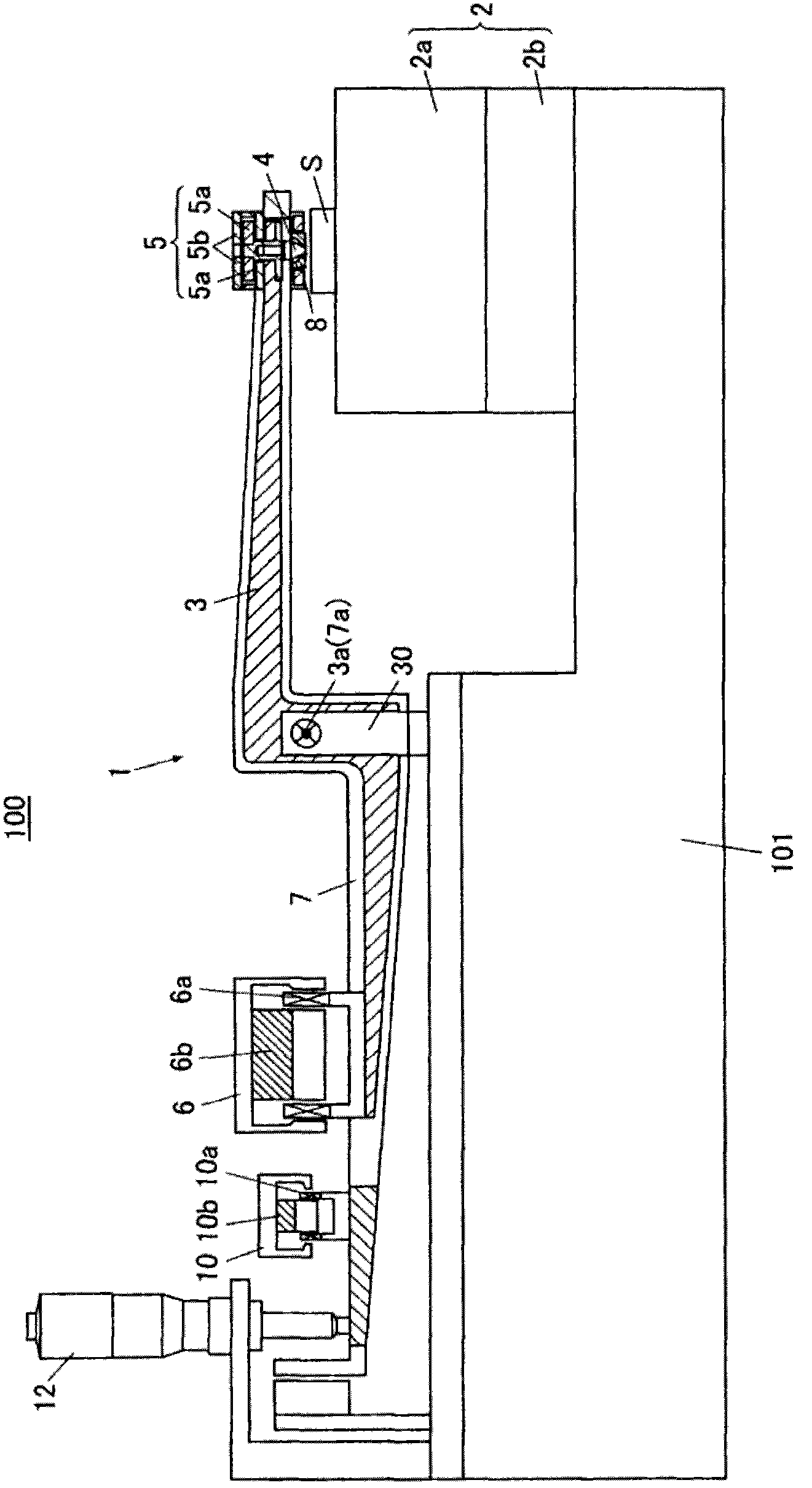
[0027] The indentation tester 100 according to the first embodiment is a rod-type instrumented indentation tester capable of continuously monitoring the test force (load) applied to the indenter 4 and the indentation depth of the indenter 4 .
[0028] like Figure 1-5 As shown, the indentation tester 100 includes a tester body 1 that applies a test force to a sample S; a controller 200 that controls various components of the tester body 1 ; a display 300 ; and an operator 400 .
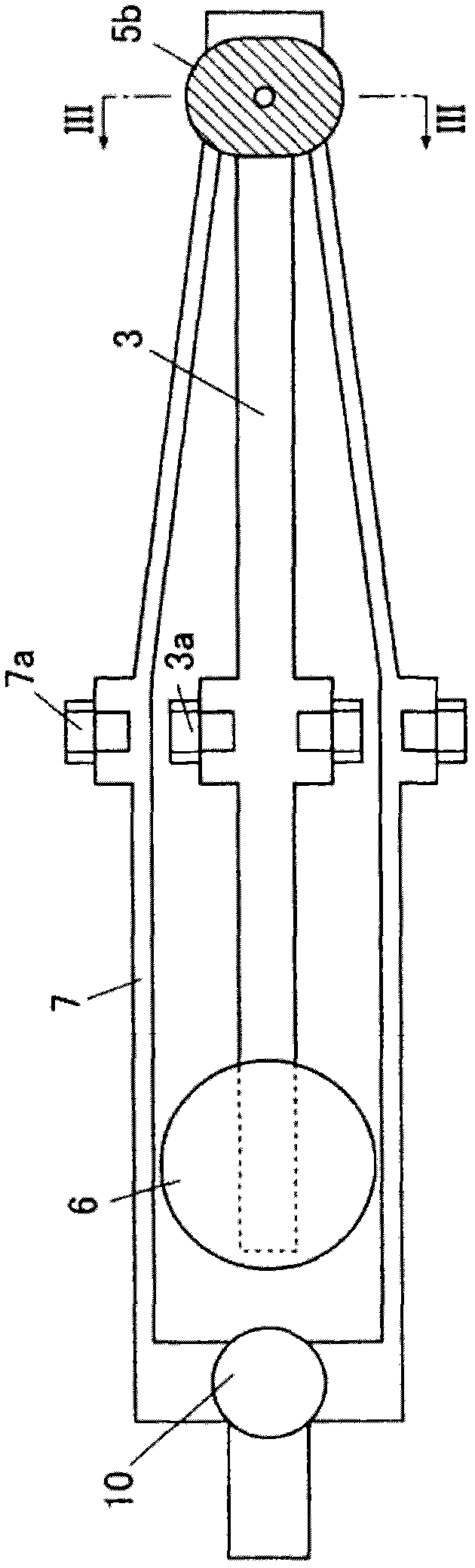
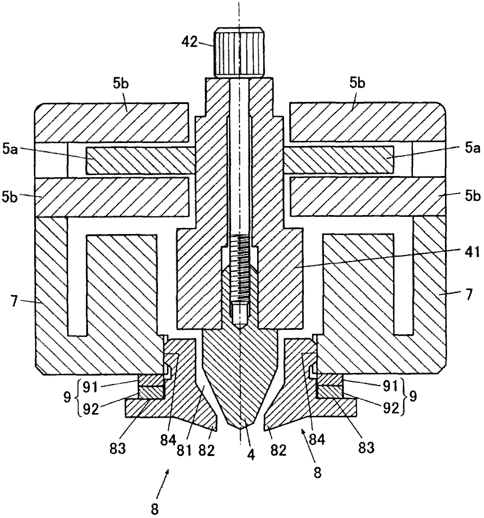
[0029] The tester main body 1 includes, for example: a base 2 on which a sample S is placed; a load rod 3; an indenter column 41; a displacement sensor moving part 5a (indenter coupling head); load applicator); reference rod 7 (pressure bracket); contactor 8 (indenter reference part); adjustment device (regulator) 9; displacement sensor fixing portion 5b (indenter position detector); second actuator motor 10 ( indenter reference portion driver); the brake 12 ; and the controller 200 that controls the...
no. 2 example
[0055] The difference between the second embodiment and the first embodiment is that the second embodiment provides the indentation tester 110 of the present invention, which is a directly instrumented indentation tester, and is different from the indentation tester 100 in that it is a rod Type instrumented indentation tester. In particular, the indentation tester 110 of the second embodiment is a direct instrumented indentation tester capable of continuously monitoring the test force (load) applied to the indenter 4 and the indentation depth of the indenter 4 . Also, in order to simplify the description, the same reference numerals are used for the structures similar to those of the first embodiment, and the detailed description thereof is omitted.
[0056] like Image 6 and 7 As shown, the indentation tester 110 includes, for example: the sample stage 21 on which the sample S is placed; the indenter column 41; the displacement sensor moving part 5a (indenter coupling head)...
example 1
[0068] Figure 8 The example shown differs from the first embodiment, for example, in the shape of the indenter 4A, the shape of the contactor 8A, and the fixed position of the adjustment device 9 . In particular, the indenter 4A has a seating surface 43A on which the adjustment device 9A can be placed, the seat surface 43 being formed in the vicinity of the circumferential outer surface of a portion of the indenter 4A in contact with the bottom surface of the indenter post 41A. The indenter 4A is thus able to place the adjustment device 9A clamped on the seat surface 43A. In Alternative Example 1, the second hollow disk 91B is placed on the seating surface 43A of the indenter 4A and the top surface of the first hollow disk 91A contacts the bottom surface of the indenter column 41A. In particular, alternative example 1 enables the indenter 4A to hold the adjustment device 9A instead of the contactor 8A.
[0069] As described above, the adjustment device 9A is configured such...
PUM
 Abstract
Description
Claims
Application Information
 - R&D
- Intellectual Property
- Life Sciences
- Materials
- Tech Scout
- Unparalleled Data Quality
- Higher Quality Content
- 60% Fewer Hallucinations
Browse by: Latest US Patents, China's latest patents, Technical Efficacy Thesaurus, Application Domain, Technology Topic, Popular Technical Reports.
© 2025 PatSnap. All rights reserved.Legal|Privacy policy|Modern Slavery Act Transparency Statement|Sitemap|About US| Contact US: help@patsnap.com